Wiring procedure for a pulsed light switch
Power saving has been a hot topic since the emergence of commercial power generation. Since the early years of electric lighting, there have been ideas for manual and automatic control of switching consumers on for the desired period and off when not in use. One of the elements of such systems is a pulse relay.
Purpose, principle of operation and application
The classical impulse relay, like a conventional relay, consists of a coil with a core, a moving system and a contact group. Such a device is often called a bistable - because it has two stable states: with the contacts off and with the contacts on. The state of the relay is maintained when the voltage is removed, and this is the main difference from the traditional system.
In real designs, prolonged presence of voltage on the coil is considered unnecessary and even harmful - the winding can overheat. Therefore, such a device is controlled by short pulses:
- the first pulse closes the contacts;
- The second pulse opens the contacts;
- The third one closes again, and so on.
Each pulse resets the contacts to the opposite state. The pulses are generated by the switches. It is logical to design the switching device as a pushbutton without locking in the pressed position.

An ordinary pushbutton device is of little use here - it is easy to forget it in the on position and after a while the coil will be out of order. Doorbell buttons can be used instead of switches.

A typical relay has inputs:
- A1 and A2 - for 220 volt power connection;
- S - control input;
- NO, C, NC - contact system terminals.
There is no unified standard for the designation of terminals. Marking of inputs may vary from manufacturer to manufacturer.
In fact, switching is not done synchronously by pressing the button - the system waits for the nearest transition of sine wave through the zero value. This is done so that the switching current is zero, which extends the life of the contact group. But such a transition occurs twice per period, the maximum delay will be 0.01 seconds, so the short pause is unnoticeable.
Many pulse relays for electric light control have additional on and off inputs. These have priority over the S input - when voltage is applied to them, the relay can be forcibly switched on or off, regardless of the state on the S terminal.
A pulse switch can be used to create lighting control systems in which lights can be switched on and off from several locations independently of other switching devices. Classically, these circuits are built on feed-through and cross-over switches, but the use of impulse switching devices has its own advantages.
Main technical characteristics
When buying a device, you should pay attention to the basic parameters:
- contact group power;
- supply voltage;
- coil actuation current;
- design of the contact group (make-and-break or flip-flop);
- additional service functions.
It is also necessary to pay attention to such (illogical at first sight) parameter, as a number of connectable switches. It would seem that the characteristic is absurd, but it is necessary to take into account the wide spread of devices with light chains. If there are many of them, the total current through these circuits will be enough to activate the relay.
The control voltage of most devices is 220 volts, but there are also relays with low voltage control (12...36 volts). Such devices have a huge safety advantage, but require an additional power supply. Therefore, such devices are not widespread in everyday life (unlike in production).
In the control circuit bistable switching devices consume very little current (this power consumption has practically no effect on the electric meter readings). This fact causes the temptation to execute the control circuits with wires with a reduced cross-section (up to 0.5 sq.mm). Remember that to protect such wires you will need to install a separate circuit breaker with a lower operating current in the switchboard. Feasibility is decided on a case-by-case basis.
Varieties of impulse relays their advantages and disadvantages
Bistable commutators can be produced in two versions:
- classic electromechanical (available in a housing for mounting on a standard DIN-rail);
- The modern electronic.
The second version allows you to reduce the size, increase the reliability of the device, and allows developers to implement virtually unlimited service functions (delay timers, WI-Fi control, etc.). The disadvantages of pulsed electronic light switches are low noise immunity.

The classic electromechanical relay is only mildly sensitive to noise and interferenceBut it is noisy and noisy in operation - the constant loud clicking sound can be annoying.
Different wiring diagrams for an impulse relay
The simplest diagram of a bistable lighting system is as follows:

If the switches are unlit, the number can be endless. In fact, there is a limit to the range of installation - at a certain length of cable, the resistance of the conductors can limit the current required to turn on the relay. But for reasonable distances, this limitation is theoretical. The number of in parallel The number of lamps connected in parallel is limited by the load capacity of the output contact group.
| Relay name | Type | Switching capacity, А |
| MRP-2-1 | Electromagnetic | 8 |
| MRP-1 | Electromagnetic | 16 |
| BIS-410 | Electronic | 16 |
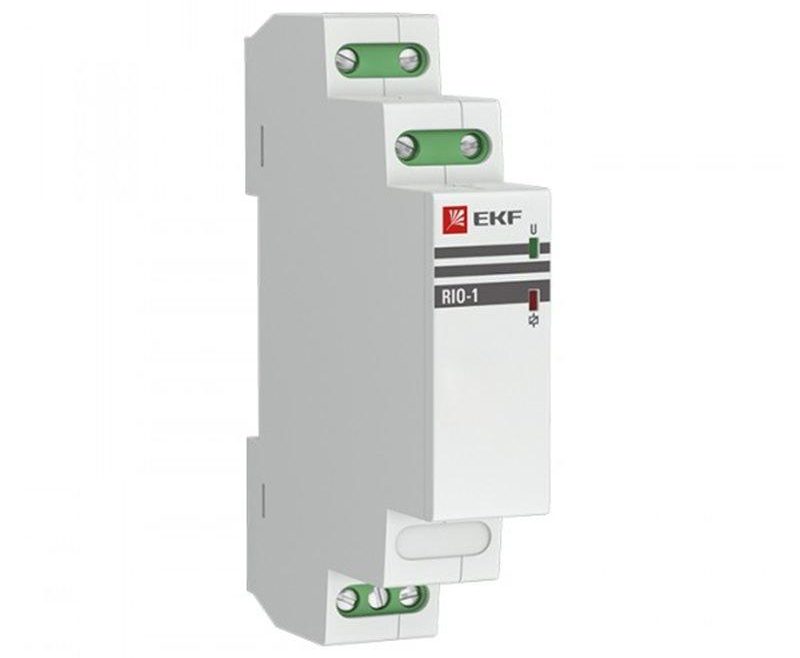
| RIO-1M | Electromagnetic | 16 |
| BIS-410 | Electronic | 16 |
From the table you can see that many relays accept loads from 1760 to 3520W. This is enough to cover almost all reasonable lighting needs (especially given the proliferation of LED equipment) without the use of intermediate relays.
Another circuit option is to use priority inputs to turn on or off. This principle is used when it is necessary to provide centralized control of lighting of several rooms or zones. When you manipulate the central control buttons, the state of the lamps will not depend on the previous position - all the lights can be turned on or off at the same time. Such two-channel switching allows you to turn on or off the lights in all rooms at once from one place, and then control the lights from the local buttons.

Installation of the electromechanical pulse device is carried out in the switchboard - it is most convenient to mount the DIN-rail there. Topology of cable laying is considered on the example of a simple scheme, and it looks like this:

Some of the connections are made with wires in the switchboard. You will also need:
- A five-core cable to run from the switchboard to the junction box (in the absence of a PE conductor, a four-core cable);
- three-core cable to the light fixture or group (two-core if there is no PE conductor);
- Push-button switches are daisy chained with a two-core cable.

If an electronic relay is used, it can be installed in a distribution box. Then the cables are routed as follows:

The difference from the previous version is that some of the connections are made in the junction box, and there is no need to lead the circuit from the switches back to the switchboard. The number of wires in the cable from the box to the switchboard is reduced: in the absence of a PE conductor two wires are enough. Therefore this scheme is generally more economically justified.
To reinforce the information on wiring, we recommend a video.
Impulse relay or crossroads switch
A control system with three or more places can also be realized by using two throughput and with several (as many positions as required) cross-connectors.

The cable routing in this case looks like this (the PE conductor is not shown). Obviously, in this case, all switches are connected to each other with a cable of three strands versus two strands.

It is also possible to do without junction box and make daisy-chain connections. In this case the number of conductors in the communication cables increases to 4, taking into account the protective conductor. Another disadvantage of this wiring is that the N and PE conductors have many connection points, which reduces the reliability and safety of the circuit.
Therefore, the circuit with a pulse relay is more economically advantageous, although not very familiar. And the greater the distance between the circuit breakers, the greater the benefit. In addition, the full consumer load current goes through the pulse switch, and in the implementation of the circuit on the pulses switched only a small control current - the durability of the buttons will obviously be higher. When designing a lighting system, you should pay attention to this option.
Operation in non-standard situations
To such situations, first of all, we should refer to the moments when the electricity in the apartment is completely cut off. When it is restored, the relays behave differently:
- For devices of the electromechanical system, de-energizing does not result in switching, so when power comes back on, the lights will be in the state in which they were caught by the disappearance of power. If the lights were on, they will turn back on, if they were off, they will remain off;
- electronic apparatuses with non-volatile memory will behave in the same way;
- simple electronics without memory will reset the state to the position specified by the developers - usually to the off position (but sometimes to the on position as well).
Another possible collision is pressing two buttons in different places at the same time. The system will perceive this as a single press, regardless of the execution of the relay, and will reset the contact group to the opposite position.
Recommended for viewing: Using relays to control lighting in the house.
The use of pulsed devices allows you to build convenient lighting control schemes that allow you to turn on the lights only when people are on site. This provides noticeable savings on electricity. Also, such schemes allow to increase the comfort of operation of engineering networks. In many cases, their use is justified also from an aesthetic point of view.