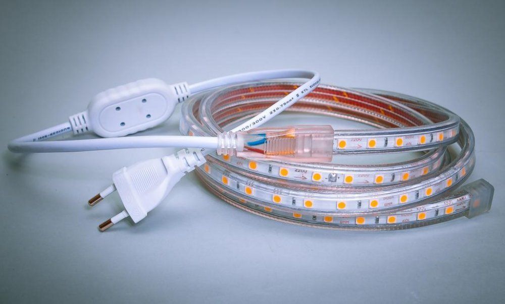
Diagram of connection of LED strip to 220V
Lighting devices in most cases are powered from the domestic electrical network of 220 V. Of the alternatives we can mention perhaps only lighting devices connected to the on-board network of cars or motorcycles. In other cases, at the beginning of the power supply circuit of the LED strip is always a 220 volt AC voltage source, whether it is a household socket or switchboard. In practice, there are different options for connecting LED lights, which depend on the parameters of the lighting device.
Features of the tape on 220 volts
The most trivial option - the use of tape designed for the full voltage of the network. However, it is extremely undesirable to directly connect the light fixture to the household network. Although the light-emitting elements have a one-way conductivity and glow during the positive half-wave sine wave, during the negative voltage is applied to them reversed polarity. LEDs are not designed to operate as high-voltage rectifiers, so the reverse voltage will be too high for them and the lifetime of the elements will be short. The LED strip should be turned on through a rectifier - preferably a bridge (two-half-period circuit).

The downside of using high voltage at equal power is a reduced current, so the sections of the ribbon can be connected in series up to 100 m total length (low-voltage fixtures - up to 5 m). Also a plus is the possibility to use conductors with a reduced cross section, but not to the detriment of the mechanical strength.
Important! The main disadvantage of this option is the extreme undesirability of using high-voltage tape indoors.
To adjust the brightness you can use dimmer - It is turned on before the rectifier. The dimmer can be either manual with a rotary button, or with remote control.
Low-voltage strip
If local conditions do not allow for 220 volts, you have to use strips for 5/12/24/36 volts. Here, too, there are a variety of ... options for connecting... to the domestic mains.
Power supply
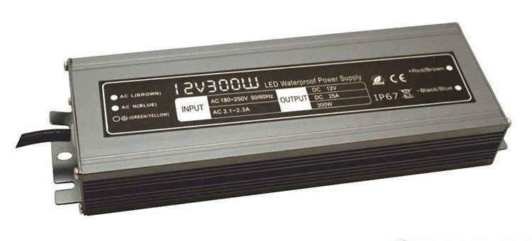
The most obvious option is to operate the lighting fixture together with a power supply for the appropriate voltage. Bulky and uneconomical sources, built on a classic scheme with a step-down transformer, have long been superseded from the field of LED-lighting by lightweight and powerful pulsed units. Therefore, the choice of PSU is made mainly by two parameters:
- output voltage;
- The maximum allowable load power.
The first characteristic is chosen simply: the voltage must match the voltage of the strip. The second depends on the load and is calculated by the formula Pbp=Rud*L*Kwhere:
- Ore - power consumed by one meter of the tape;
- L - total length of the belt sections;
- К - is a safety factor equal to 1.2...1.4.
The result is rounded up to the nearest standard value. If the power supply unit does not indicate the power, but the maximum allowable current, it can be recalculated into the power according to the formula Pbp=Imax*Uv.
With ballast
Connecting LED strips to 220 V without a power supply is possible, but undesirable for safety reasons. Each point of the circuit will be under full line voltage, so all manipulation must be done with the full disconnection of the strip. But if safer options are not available, you can connect to the network through a resistor that will extinguish the excess voltage. Its rating is chosen so that at the operating current (determined by the power of the lamp) the difference between the mains voltage and the rated voltage of the strip would fall on it:
Rb=(mains-Unom)/(Inom)where:
- Rb - is the value of the ballast resistance;
- U mains - line voltage;
- Unom - rated voltage of the tape;
- Inom - rated belt current, calculated according to the formula Rud*L /Unom.
Important! In this calculation you must use the amplitude value of the mains voltage of 310 V.
If you set nominal voltage of the tape to 5 volts, power of 1 meter of the tape to 10 W and the total length of 5 m, you can calculate the value of Rb:
Rб=(310-5)/((10*5)/5)=305/10=30,5 Ом. You can take the nearest standard rating of 33 ohms. At first glance, this connection is much cheaper and easier than with the power supply.

In fact, everything is not so rosy. First, you must calculate the power dissipated by the ballast as current multiplied by voltage (here we take the effective voltage value of 220 V):
Pb=Inom*220V = 10A*220V=2200W. It is difficult to find a resistor of such power, and its dimensions will be appropriate. And as the web power increases, the calculated resistance will fall and the dissipated (wasted!) power will increase, so this method is only suitable for low-power luminaires. This problem can be circumvented by using a capacitor instead of a resistor as the ballast. Its capacity is calculated by the above formula:
C=4,45 (U-network-Unom)/(Inom), where C - capacitance in μF.

The capacitor must be rated for at least 400 V, and two resistors must be added to the circuit:
- R1 - with a resistance of a few hundred kilohms to discharge the capacitor after it is turned off;
- R2 - to limit the charging current at the moment of switching on, its nominal value can be a few tens of ohms.
But this is not the only problem:
- Mention has been made of electrical safety issues in the operation of tapes with this connection. Therefore, only silicone-encapsulated tape can be connected in this way, and the connection points must be carefully insulated. And it is not a good idea to use such a connection in wet areas (swimming pools, baths, aquariums).
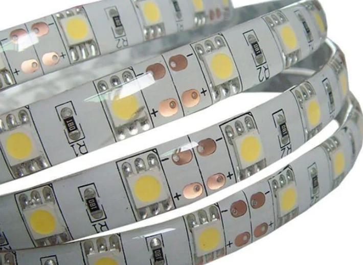
![Options in silicone sheathing]() Silicone-sheathed versions are not afraid of water, but they get much hotter.
Silicone-sheathed versions are not afraid of water, but they get much hotter. - The calculation is only correct for a certain tape of a given length. The ballast must be recalculated at any replacement or change of the length of the webbing.
- The mains voltage in normal operation may deviate within 5%, the maximum allowed is 10%. The most common resistors are also accurate to within 10%. Taking into account the variation of strip parameters relative to the stated ones, the strip voltage (and the current through the LEDs) can differ significantly from the calculated ones, even if the calculations are refined by actual measurements - simply because of the fluctuations of the mains voltage. The result can be, on the one hand, a decrease in the brightness of the luminescence, and on the other hand, the failure of the luminaire due to overcurrent. This problem is manifested the more clearly the lower the supply voltage of the strip. If you use a capacitor, the problem is only exacerbated, because a number of capacitance ratings are less frequent than a number of resistances, and the actual accuracy is lower.
- When using a dimmer to control brightness or a controller to control the color of the RGB ribbons current through the LEDs will change, at the same time the voltage drop across the ballast will change, which will also exacerbate the instability of the voltage drop across the strip in sync with the change in current. Therefore, the use of devices to regulate the intensity of radiation is excluded.
Due to the combination of problems, such a connection should be used only if it is completely impossible to use a power supply for the corresponding voltage.

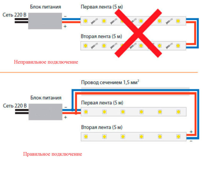
If several pieces of fabric with a total length of more than 1 meter are used, they must be connect in parallel. Otherwise, the ribbon conductors will not be able to handle the total current of the lighting system. Better yet, calculate the ballast for each section separately. If replacement is necessary, only the webbing to be replaced will be recalculated. The diode bridge must be able to withstand the total current of all sections of the strip.
Typical wiring mistakes
The most common mistake made when connecting a strip to the mains via a power supply is to make the wrong calculated power. It is ideal to measure the actual current consumption with an ammeter, recalculate it into power and compare it to the maximum power of the power supply when you connect it for the first time. This procedure should always be done if the power supply starts to make abnormal noises when switching on, there are signs of excessive heating, etc.

When using a power supply it is very desirable to provide a switching device on the input side and on the output side. On the high side, disconnection can be accomplished by simply pulling the plug out of the socket. In the case of a fixed connection it must be possible to remove the voltage from the input by disconnecting the circuit breaker (it must always be present!).
It is not necessary to observe phasing (connection of zero and phase to the corresponding terminals of the PSU).It does not affect the performance - there is a rectifier at the SMPS input. But it is necessary to disconnect the phase conductor or the phase and neutral conductors at the same time when switching (when connecting through a socket it is done by itself). The PE conductor (PE) must always be connected if available - this is the only way to ensure operational safety. The protective earth connection must not be interrupted.

With a transformerless connection the importance of measuring the actual current is even more important. But instead you can measure the actual voltage at the tape contact pads the first time you turn it on. If it deviates strongly from the rating, you must adjust the ballast rating to the appropriate side. If the voltage at the consumer is lower than necessary, you must reduce the resistor rating or increase the capacitor capacity. If the voltage is higher, then do the opposite. Measurement should be done with caution, without touching the uninsulated parts of the multimeter's probes.

Also for low-voltage tapes it is a mistake to use connecting conductors with a cross-section smaller than that required for the existing current. During operation, you should pay attention to the temperature of the wires (ideally, if you have a pyrometer, thermal imaging camera or other diagnostic equipment for this purpose). If increased heating is observed, We need to replace the conductors with thicker ones.. In order not to make a mistake initially, you can use the cross-sectional table.
| Cross-section of copper conductor, sq.mm | 0,5 | 0,75 | 1 | 1,5 | 2 |
| Maximum allowable current with open laying, A | 11 | 15 | 17 | 23 | 26 |
See for sure: LED strip 220 volt top or junk, what is better and worse than 12 volt strip.
You can connect the LED strip to 220 V in a variety of ways. But the best way is still the use of a switching power supply. All other methods are alternatives in hopeless cases.