Voltage stabilization of low beam headlights
In recent years, motorists began to equip their cars with daytime running lights. Although the rules allow the use of standard lighting fixtures (fog lights, headlights, etc.), many people prefer to perform the headlights in the form of separate units. And some motorists are faced with the fact that the LEDs, on the basis of which the lights are made, fail, not working for a year. The reason for such a short life no one has not figured out in detail. Perhaps it has to do with the quality of LEDs from unknown manufacturers, or with the fact that the manufacturers are far overestimating the declared resource semiconductor products, and maybe it's all about the lack of cooling.
But there is a strong belief that the LEDs fail due to unstable voltage on-board car or because of short-term spikes in the power supply circuit, the amplitude of which reaches several tens of volts. To escape from this misfortune is trying to install a stabilizer cab voltage for the car's flasher lights.
How many volts must be the stabilizer
If the stabilizer for LEDS is used with industrial lights, its output voltage must be equal to the supply voltage marked on the housing of the device. In most cases it is 12 volts. For a homemade system, you need to consider its circuit.

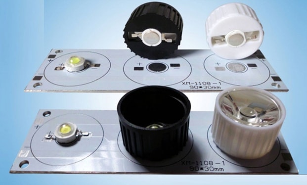
It usually consists of in series of 2 to 4 LEDs in series and a quenching resistor. For a LED to work properly, it must have its rated voltage dropping on it. For example, for an ARPL-Star-3W-BCB LED the voltage drop is 3.6 V. For a chain of three elements, you must provide 3.6*3=10.8 volts. Another small voltage drop should be at the ballast (its value is determined in the calculation, 1...2 volts). All in all you get about 12 volts.
| LED type | Power, W | Voltage drop, V |
| TDS-P003L4U13 | 3 | 3,6 |
| TDSP005L8011 | 5 | 6,5 |
| ARPL-Star-3W-BCB | 3 | 3..3,6 |
| STAR 3WR | 3 | 3,6 |
| High Power 3W | 3 | 3,35..3,6 |
What kind of voltage regulators for LEDs
The simplest and cheapest stabilizers are of the linear type. They redistribute the mains voltage between the regulating element (transistor) and the load.

If the input voltage decreases or the load current increases, the transistor opens and the load voltage increases. If the input voltage increases or the load current decreases, the regulator closes the power element slightly and the load voltage decreases. This is how stability is achieved. The advantages of such stabilizers are:
- simplicity;
- low cost;
- you can buy an integral version for a fixed voltage.
Among the disadvantages are high power losses due to dissipation at the regulating element (therefore, an effective heat sink is required) and the need for the input voltage to be higher than the output voltage.
Pulse stabilizers are free from these disadvantages, they distribute energy over time, but their problem is the complexity of making them. For self-assembly you need certain knowledge and qualification.
How to choose the right one
To select an industrially manufactured device, it is necessary to set the following parameters:
- output voltage;
- operating current;
- minimum input voltage (the maximum voltage is usually a few tens of volts, such a voltage in the car network does not exist).
How to select the output voltage is described above. The operating current must exceed the consumption current of the lanterns (or lantern, if the stabilizer is placed on each device separately) with a reserve. Few people pay attention to the latter parameter, and it can have a critical impact on the performance of the entire system.
Read also: How to choose the right running lights on the car, so as not to be fined
Let's study popular voltage regulator circuits
First of all you have to choose the circuit of the device. There are a lot of recommendations in the global net to assemble such blocks on integral linear regulators 7812 (KR142EN8B).

Those who publish such schemes, pay attention to their simplicity and lack of tuning, completely forgetting about one problem. For normal operation at least 2.5 volts must drop on such a regulator - it is written about it in any datasheet. Simply, for any effective stabilization at the output, the input must be at least 14.5 volts. In a car with a good alternator there should be no such voltage, and at a lower value it makes no sense to use such a circuit. As a compromise, you can use a nine-volt stabilizer (LM7809), its performance will start from 11.5 volts at the input, but the brightness of the lights will drop. According to GOST requirements, the minimum light intensity should be 400 cd, and you can't go below this limit.
The recommendations to put a diode at the input look even more thoughtless.

Its purpose is very doubtful - it is not necessary to protect the chip from reverse polarity in a stable mounting. But the silicon p-n junction will drop another 0.6 volts, and you need at least 15 volts for normal operation.
Circuits with an integrated 12 volt ruler (with or without a diode) are useful except for cutting off high voltage spikes on the +12 volt bus (if they are really present). That is, they can serve as a kind of "Zener barrier", but such barrier can be made much easier. It is necessary to include in parallel to the chain of LEDs a stabilitron Ust, slightly higher than the operating voltage. In normal mode, its resistance is high, it will not affect the operation of the illuminator. If the stabilization voltage is exceeded (e.g. 15 volts) it will open and "cut off" the excess.

Slightly better stabilizers work with LDO (low drop out) chips. This looks like regular linear regulators but you need only 1.2 volt drop out for them to work properly and they stabilize effectively at 13.2 volt. Which is better, but still not enough for normal operation. The LM1084 and LM1085 are suitable for this circuit, but the circuit diagram is a bit more complicated.

To get an output voltage of 12 volts the resistor R1 must be 240 ohms and R2 must be 2.2 kOhms. There is a fundamental obstacle to reduce the drop further - the regulator is made on a bipolar transistor, and on its emitter and collector junctions must drop at least 1.2 volts. This is easily circumvented by using a field-effect transistor as a regulating element. Integrated circuits based on this principle are difficult to find, even more difficult to find the right parameters and more expensive. But to make such a device on discrete elements is possible even for an amateur radio operator of average qualification.

The elements are rated:
- R1 - 68 kOhm;
- R2 - 10 kOhm;
- R3 - 1 kOhm;
- R4,R5 - 4,7 kOhm;
- R6 - 25 kOhm;
- VD1 - BZX84C6V2L;
- VT1 - AO3401;
- VT2,VT3 - 2N5550.
The output voltage is set by the ratio R5/R6. With the specified ratings the output will be 12 volts, the input will need no more than 12.5 volts. This is a serious improvement. But a fundamental jump can only be achieved by using a switching power supply. You can build such a step-up converter using the XL6009 chip.

Such a stabilizer in ready-made form can be ordered on popular Internet sites. But there is a problem - manufacturers out of economy often install elements designed for a current of not more than 1 A (although the chip is able to deliver a current of up to 3 A). Or, for example, input or output oxide capacitors may not be installed. Even the Schottky diode N5824, mentioned in the datasheet, starts to get warm at currents above 1.5 A. Instead of it you should use a more powerful diode, for example SR560. All these replacements and simplifications lead to overheating of the board and its failure.
The video shows an example of assembling a 12 volt regulator.
Fabrication Considerations
To manufacture will require electronic components for the selected circuit. You can buy them in specialized stores or on the Internet. For a device on an integrated linear stabilizer, the case is not needed, but you need to take care of the heatsink. You will also need a heatsink when making a linearizer with discrete elements. More complex devices must be assembled on circuit boards. Those who know home technology can design and etch a printed circuit board by themselves. For others, it is better to use a breadboard - cut off the necessary piece and mount the elements on it.

You must also select or assemble the case, not forgetting about the heat dissipation. Putting the board in a heat shrink is not the best option in this regard. You will also need a soldering iron with a set of supplies.
It is difficult to give general instructions on how to make - it all depends on the circuit chosen and the technology preferred. But it is possible to give some advice to those who have little experience in making electronic devices:
- All connections must be carefully soldered (taking care not to overheat the elements and conductors in the insulation) - operating conditions will involve shaking and temperature fluctuations, and poor quality soldering will immediately make itself felt;
- the housing must be designed to prevent water and dirt from getting inside - when installing the device under the hood, these substances will be enough;
- if the housing is not used, the soldering points must be carefully insulated - for the same reasons;
- After assembly and functional testing it is not superfluous to varnish the board on the soldering side and dry it.
Only a careful approach to manufacturing can guarantee at least some long-term operation of the self-made in harsh conditions.
Installation on the sidelights
Stabilizer, regardless of which circuit it is assembled according to, is installed in the gap of the wire going from the switch or controller to the daytime running lights. This can be done in any convenient location. If the power of the regulator is enough to work with two lights, you can plug it in the gap of the power wire of the two lights, up to the point of separation. If not, you will need two devices for each lamp.

You have to remember to connect the minus wire to the common conductor of the car. Another issue that often comes up is the installation of a heatsink for the line regulator. There is an idea to use the car body as a cooling element. Its area is large, and it will do a great job of dissipating heat. Provided that there is good thermal contact between the surface of the chip and the surface of the body. And this will require at least the removal of the paint coating in the place of installation, as well as drilling a hole for the fixing screw. In this place will quickly form a hotbed of corrosion. Therefore, this idea is not the most successful. It is better to make a small separate heat sink from a piece of sheet aluminum.
Video: Connection and testing of L7812CV and LM317T stabilizers for LED daytime running lights on VAZ-2106.
The question of using a stabilizer for daytime running lights is not as simple as it seems at first glance. To make a decision on its application and choose the method of installation requires a certain technical preparation. The review materials will help to make this choice.