How to properly connect a photo relay to street lighting
A photoelectric relay is a device that operates when ambient light reaches a certain threshold. As soon as the light flux reaches the set level, a signal is generated in the form of closing/opening of relay contacts, appearance of voltage on terminals, etc. This signal can be used to control actuators and electrical devices. This device is often incorrectly called a photosensor. In fact, a sensor is a device for converting one quantity into another. In this case, the sensor is a photosensitive element as part of a photocell.
The obvious domestic application of the device is automatic control of outdoor lighting (street or local). The device itself will turn on the light when it gets dark, and will not forget to turn it off at dawn. The industry produces devices optimized for this task. You can install, connect and configure the photo relay yourself.

How the photosensitive automat works
The device that triggers when the illumination changes to a threshold value, can be made on a different element base, but has approximately the same structure.
- As a photosensitive element can be used a semiconductor device, changing its parameters or generating an EMF under the action of incident light. For example, photoresistor changes its resistance when exposed to photons, photodiode generates an EMF, etc. Sensor of light level can be built in the device body or be external.
- Transducer transforms variable value into electric parameter, which is convenient to work with. If a photoresistor is used as a photocell, its resistance is converted into voltage.
- The amplifier amplifies the voltage to values at which the level of interference and interference becomes insignificant.
- The threshold device compares the set voltage value with the voltage coming from the amplifier. If it becomes higher or lower than the reference level, the comparator changes its state from one to zero or vice versa.
- Delay Timer. Prevents the relay from triggering if the duration of the control signal is less than the preset duration.
- Actuating device. When the state of the comparator changes, caused by the light passing through a predetermined threshold, it outputs a control signal that can be used to control external devices. In most household devices, this signal is a "dry contact" of the built-in electromagnetic relay. But it can also be a discrete voltage from a solid-state switch, a change of state of a transistor with an open collector, etc.
Some units can be combined. For example, a converter and an amplifier are combined into one circuit. There may not be a delay timer in simple relays, but it has a useful function, which is discussed below. There can be different element base - analog design or digital. But the principle of operation remains: comparing the actual light level with the set threshold and issuing a control signal.

Selection criteria for the device
To choose a photo relay, it is necessary to take into account several points:
- The supply voltage. It does not fundamentally affect the consumer qualities, but it is convenient to power the device from the same voltage that is used for the controlled lighting device. It is even more convenient to have a light sensor with double power supply - from 220 volt and from low DC voltage.
- The design of connecting a light sensor to a street light relay. The photocell can be built-in and remote. The first option is cheaper, the second is more convenient to install.
- The power of the output contact group. If it does not allow you to switch the existing load directly, you will have to connect it through an intermediate relay or magnetic starter.
- Degree of protection. Depends on where the main unit is supposed to be installed. If it is installed indoors, IP40 is sufficient. If outdoors, IP42 or IP44 and in some cases IP65 are required.
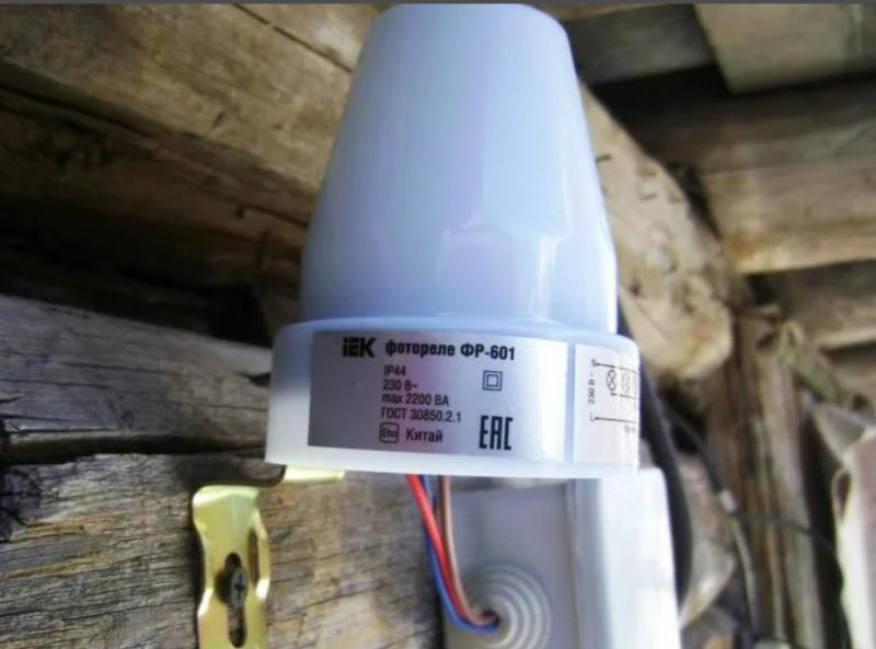
| Type of photo relay | FR-601 | Euroautomatics F&F AZH | Smartbuy | FR-05 |
| Load capacity, W | 1100 | 1300 | 2200 | 2200 |
Other characteristics (delay regulation range, etc.) are chosen according to local conditions and are not of principle nature.
Device wiring
In many cases, the wiring diagram for a particular relay with indication of terminals is printed directly on the device case.

The example of the FR-M01 relay shows that the relay is connected to:
- photosensor to terminals T1, T2:
- DC supply voltage of 24 volts to terminals A2, +A3$;
- when powered from the mains AC voltage of 220V is fed to A1, A2 (the device has a dual power supply circuit);
- terminals 11,12,14 are used for load control.
Other photo relays for street lighting have a similar wiring diagram. You just need to make sure that the load power does not exceed the load capacity of the output contacts. In this case it is equal to 16 amperes at a switching voltage of 220 volts (not the supply voltage of the photo relay!) or 30 volts DC. This is high enough load capacity, but if it is not enough or you use a low-power relay of another type, you can control a powerful load through an intermediate relay or a magnetic starter.


The principle is simple - the photo relay controls the starter, and the powerful contacts of the starter switch a lamp, an electric motor of an irrigation pump, etc.

You can connect an additional switch and turn on the light independently of the photo relay. Another scheme allows you to turn off the light even if the light control device gives a command to turn it on.

There is also a wiring scheme for completely independent control, allowing you to turn lights on and off at will, regardless of the state of the relay. The problem is acquiring a household switch with a change-over contact. You can use an industrial switching element, but there is a question of aesthetics. The photo relay must also have a flip-type output contact.
Setting the photosensitive device
After connecting the light-sensitive relay you need to adjust its tripping level. This is done experimentally. Minimum sensitivity is set - the knob is turned to the extreme position, the light bulbs should not be lit (if they are lit, it means that the highest sensitivity is set). Next, you need to wait until the light level falls to the level at which it is desirable to turn on the lights. After that you should turn the dial to the side of sensitivity increase until the light turns on.. The next day you should check the moment of actuation and, if necessary, adjust it more accurately. In the morning the light will go out at approximately the same level of illumination.

Important! To avoid multiple actuations at light levels close to the threshold, most devices have a hysteresis - the on level is slightly lower than the off level. This should be taken into account when adjusting the device.
Advanced devices have a teach button. When the desired light level is reached with this function, the photo relay will memorize the set level, and will then trigger when the recorded threshold is reached.
If the relay has an adjustable delay timer, its timing should also be chosen experimentally to avoid turning on the light when the light level rises for a short time. For example, when the light from headlights of passing cars hits the photoelectric sensor.
Video: Detailed overview and adjustment of Proxima PS-3 photoelectric relay.
Mistakes when connecting and installing the light barrier relay
The wiring diagram of the photo relay is quite simple. To avoid mistakes, it is sufficient to simply check the installation. Problems in most cases are due to incorrect installation of photo sensors.
Often installers get carried away looking for a convenient place to mount the remote photocell and exceed the allowable cable length. To avoid this, it is enough to carefully read the instructions before starting work.
The light sensor itself should be installed taking into account simple rules. Failure to follow them can add problems instead of the comfort of lighting control:
- Do not install the photoresistor in such a way that it is exposed to light from artificial sources - lights of the neighboring area, etc., otherwise it will perceive such illumination as the onset of morning;
- on the contrary, do not place the light-sensitive element in the shadow zone at sunrise - this will cause a delay in activation;
- the surface of the photosensor must be protected from dust, precipitation, etc., and if this is not possible, you must regularly inspect the element and clean it.
Video lesson: Wiring diagram and principle of operation of IEK Photo Relay ФР-602.
Rules are not complicated, but it is much more convenient to perform them when using a relay with remote photocell. And the executive unit itself can be mounted where it is more convenient to connect it to the lighting control circuit - for example, in the power cabinet.