How to repair a chandelier with remote control
In recent years, chandeliers with remote control have become popular. Their advantage is not only that the light can be controlled from the comfort of one's seat. Replacing a single-arm chandelier with a multi-arm chandelier with the ability to separately control the light-emitting elements in the usual way leads to the need to replace electrical wiring, open up the decorative finish of the walls, etc. Chandelier with a remote control can be easily connected in place of an ordinary lamp. You can buy such a device as a complete set, or you can buy a kit for independent installation in a ready-made chandelier.

With all the advantages of such a solution, a lot of trouble to the owners is the low reliability of such devices. But they can be repaired, having a minimum set of tools and initial qualification.
Diagrams of chandeliers with remote control
Before we talk about the repair of a faulty chandelier with remote control, it is necessary to find out how the system functions as a whole. This will help to diagnose the problem and save time.
The general scheme of remote control of the chandelier is based on the same principle as the remote control of any household electronics with one difference - the chandelier is controlled not by IR, but by radio channel. This is due to the fact that conventional infrared communication channel can clog the interference from a nearby powerful light source.

The transmitting part generates a command in the form of a sequence of pulses emitted by the antenna. On the side of the chandelier are the receiving part, consisting of:
- The receiving antenna, in which an EMF from the electromagnetic signal of the transmitter is induced;
- The receiver itself, which converts the EMF into a sequence of electrical pulses;
- The signal decoder, which, according to the command, selects which illuminator should be switched on or off.
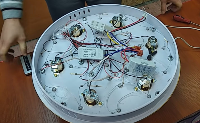
The actuating part is the transistor keys that control the electromagnetic relays. The contacts of each relay turn on the lighting fixture, which can be LED or based on energy-saving lamps (one chandelier can use both elements). Incandescent lamps are not used in such lighting fixtures because of the high power consumption and the need for relays with reinforced contacts.
The transmitting part looks like a remote control of home electronic appliances and is built according to a similar principle. The only difference is the transmitting antenna instead of the infrared LED.

The work of the receiving and executive parts will be disassembled on the example of a typical circuit of a chandelier with two lamps. Other lighting devices are built on a similar principle.
The power supply circuit is built according to the transformerless principle. The capacitor C2 dampens the excess voltage. Then a bridge-type rectifier with a smoothing capacitor is installed, so a constant voltage of 12 V is obtained to power the relay windings. To provide a stable 5V voltage for the low-current part, an integrated regulator DA1 is used. This supplies the RF receiver and the decoder.
The YDK-30 module serves as a radio (RF) receiver. It converts the EMF induced in the antenna into a sequence of pulses with an amplitude sufficient to operate the decoder. The decoder is built on the HS153 chip. Upon receiving the command, the decoder turns the corresponding transistor key on or off. This key in turn controls an electromagnetic relay which gives voltage to the corresponding luminaire. The luminaires are built on LED or halogen bulbs with the appropriate driver or electronic control gear.
Important! Almost all circuits of the receiving and executive parts of the remote control system made in China (even with assurances on the package that the device is designed in Germany) have a transformerless power supply circuit with quenching resistors or capacitors. When repairing or checking the circuit it is necessary to keep in mind that all elements are under full voltage of 220 V. Failure to comply with health and safety requirements may result in electric shock.
Chandelier with remote control malfunction
Before you start repairing a chandelier with remote control, you need to make a thorough diagnosis and identify the faulty element. To fix the lamp "by the scientific method" - not the best idea. This can lead to unjustified financial and time costs.
The chandelier doesn't turn on with the remote
If the chandelier does not respond to pressing the buttons on the remote, the first thing you should check in this case - whether the batteries are alive. You can measure the voltage on them, you can immediately replace the galvanic elements.
Then two possibilities are possible:
- The remote control is defective;
- The receiver part is faulty.
In the first case, you should try to find a remote control from a similar chandelier and try to control it. If everything is okay, you should repair the remote. If not... You can definitely determine the functionality of the transmitting part only if you know its working frequencies and if you have a radio receiver for these frequencies. It is easier to find another remote or rely on your intuition.
If your intuition tells you that the malfunction is on the chandelier side, you should start by checking for power. The probability of all transistor switches and relays failing at the same time is very low.But the individual elements in the power supply circuit can fail. You should check the voltage at the smoothing capacitor after the diode bridge. If it differs much from 12-15 V, then it is necessary to diagnose and repair the rectifier. If everything is OK, check the voltage at the output of the integrated regulator - in this case +5 V. Measure carefully, remembering that all radio elements are under voltage of 220 V.
If voltage is present, it is necessary to make sure that there are pulses occurring at the output of the receiver when you press the remote control buttons. This can be done with an oscilloscope. If it is not available, you can try to make a simple LED probe.

If you are lucky enough to see LED flashes, then the RF receiver is good.
Important! Before you check the circuits with an oscilloscope, you must make sure that its input is rated at at least 310V (the amplitude voltage of the mains). Otherwise, any wiring error may damage the unit.
If there are pulses at the RF module output (decoder input), it is necessary to check the response of the decoder to the commands. The outputs controlling the transistor switches should show and go out of the one level when the remote control signals are applied. You can check this with a multimeter in voltmeter mode or with the same probe.
Video lesson: Circuit diagnosis and repair of an LED chandelier with remote control.
The chandelier clicks but does not turn on
If you can hear the clicks of a relay when you give commands through the remote control, it means that the problem is:
- transmitting part;
- Power supply circuit of the receiving and executive parts;
- decoder;
- Transistor keys and relay windings.
And the light-emitting elements (their electronic circuits) or the relay contacts may be faulty (burned out). Since simultaneous failure of all lamps is unlikely, the cause should be looked for in the contact group - here simultaneous burning out looks more real. The reason may be the mismatch between the operating current of the relay contacts and the current consumption of the lamps. Over time, this leads to a loss of conductivity.
If the relay can be disassembled, you can try to clean the contacts. If not, it is necessary to replace the relay.
It is possible to replace the element with one of the same type, but it does not make much sense - after some time the contacts will fail again. You should try to choose a more powerful relay, as far as space and installation dimensions allow. Some types of relays and currents switched at 220 V AC are given in the table below.
| Relay type | HRS-4H | SRD-12VDC | SRA-12VDC | JS-1 |
| Rated current, A | 5 | 10 | 20 | 10 |
Important! It is not a good idea to use car relays as a substitute for regular relays or for self-made relays. Their windings consume too much current, and contacts are not designed for switching voltage of 220 V.
Also in some cases, there is a violation of soldering of relay contacts due to constant heating. Before replacing, carefully examine the pads where the contacts are soldered, and try to ...try to solder... .. Sometimes this helps.
Thematic video:LEDs
Improper operation of the remote
It happens that some of the lamps are controlled by the remote, and some do not respond to button presses. The reason may be the physical wear and tear of the buttons. Radical way is to replace the remote. You can search for repair kits for repairing remotes in stores or on internet marketplaces. These kits include spare contacts for the buttons.

There are also reports on specialized forums about chandelier malfunctioning due to a poor quality film capacitor in the power circuit. In this case, channel 1 continues to work, channel 2 and 3 do not. It is easy to fix - you just need to replace the capacitor.
LED's and light bulbs don't light up
If everything is working, but some of the LED or halogen bulbs stop glowing, then you have to look for the problem in them or in the drivers (electronic control gear).

Sometimes one element in a chain of LEDs burns out. You can find it with a wiretap and replace it. Or simply short-circuit it in the hope that the driver will pull it out. You should not put too much faith in this method because in many luminaires in order to save space and reduce the cost instead of a full-fledged driver put damping resistor. But to diagnose and repair of such a "driver" easy. It is enough to check the resistance with a multimeter. If the LED-light uses a full-fledged current regulator, its repair will require instruments and skills.

Functionality halogen bulbs can be checked by replacing them with known faulty elements. The electronic transformer that powers the lighting element can be replaced or repaired.

All semiconductor elements (transistors, diodes) can be checked in a row. The winding elements will usually show signs of burning when they fail. To find the fault of the other parts, you will have to work with instruments. First of all, localize the fault by checking the presence of a constant voltage of 220 V at the output of the bridge. Next, use an oscilloscope to check for oscillations at the output of the pulse transformer and, using the information obtained, find the faulty element.
Other malfunctions
During the operation of chandeliers, other malfunctions can also occur. The description of all possible options is endless and is beyond the scope of the review. Therefore, in each case, you will have to look for them on your own. It is not always easy, you will need to include ingenuity, read technical literature. But this is the only way to improve skills.
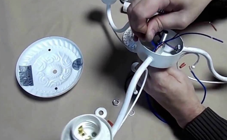
Repair of a chandelier with a remote control with their own hands
After qualitatively performed diagnostics, the repair will not be difficult. It boils down to replacing the identified faulty element. You can buy these components at electronic component stores or on the Internet.
Chandelier control unit replacement
If diagnostics of the controller did not give you clear results and the owner thinks that it is not reasonable to buy a new receiving and transmitting part set, you can change the chandelier to local control from a two-button light switch. It is advisable to do this conversion if the chandelier with remote control is installed in place of the chandelier, which used to be switched this way, and the appropriate wiring is already in place. Otherwise, you will have to conduct additional wire, and it is opening up the decorative lining of the walls and ceilings, drilling, etc.

If the wiring is already ready, you can connect the light fixture without interfering with the internal circuitry by means of the available terminal block for external connections. The advantage of this option is that if the owner decides to replace the controller in the future, rewiring will be minimal.
Experience shows that if a chandelier with remote control fails, it is quite realistic to give it a second life. You will need a small tool kit, basic knowledge of electrical engineering and the desire to think.