How to connect a light bulb through a switch - schematics
The light switch is a common household appliance. It is designed to make, break (and in some cases switch) the electrical circuit of lighting. You can connect the switch to the light bulb yourself, but it does not hurt to get acquainted with the proposed materials beforehand.
Types of light switches
It is possible to classify household switching devices on various grounds. First of all, they are divided according to their purpose. It is determined by the type of contact groups, their number. The most common devices - key. They have a contact group for closing-opening of the electric circuit. According to the number of contact groups, such devices are divided into:
- single-key - with one contact group;
- two-key - with two independent groups;
- Three-key switches - with three keys.

Also there are loop-through and cross-over devices to create light control schemes from several points.

According to the method of action they can be divided into:
- key-operated;
- pushbuttons - with a non-latching button to control lights via pulse relays;
- rotary - in order to turn on the light the control device must be turned;
- Sensor-based, remotely controlled, etc. - For creating systems such as "Smart home».
According to the type of installation switches are divided into:
- external - used with open or concealed wiring;
- Recessed - used for concealed wiring.
According to the degree of protection switches are divided into devices for indoor and outdoor installation (IP no less than 44). Also when selecting should pay attention to the rated current - it must overlap the current expected load.
Preparation for operation, equipment selection
To successfully connect an electric light bulb you need certain materials and tools. Without these, there is no quality that sets the longevity of the system.
A set of necessary tools
To perform the installation will be required:
- an assembler's knife for removing the insulation;
- If an insulation stripper is available, it will come in handy for stripping individual conductors;
- To shorten cables, wires to the required length, wire cutters are needed;
- a set of screwdrivers will be needed for installing electrical devices;
- if soldering of stranded wires or servicing of stripped sections of wires is planned, you will need an electric soldering iron with a set of consumables (flux, solder).

Conductor Products
When selecting cable for the lighting system, you must take as a basic rule - no aluminum. The relative cheapness of aluminum conductor products is counterbalanced by potential problems in future operation:
- the ductility of this metal leads to deterioration of contacts in clamping terminals, they will need to be periodically retightened;
- its brittleness will lead to problems in subsequent repairs;
- its tendency to oxidation in the air will also not improve the contact (copper is also not free from this disadvantage, but here the problem can be radically solved by deburring the stripped areas).
In addition, the specific resistance of aluminum is 1.7 times higher than that of copper. Therefore, it is necessary to choose conductors with a larger cross-section. This also somewhat levels out the financial savings.

As for the cross section of conductors, it is selected by economic current density and tested for thermal and dynamic resistance to short-circuit currents. It is also required that the voltage drop on the supply conductors not exceed 5% for the farthest consumer. But in most cases it is not necessary to do the calculation. Many years of experience have shown that A cross-section of 1.5 mm² (for copper!) is suitable in 99+% cases of arrangement of lighting networks. Only in rare situations (extra-long lines, etc.) should you check the voltage drop and the phase-zero loop resistance. It may be necessary to increase the cross-sectional area. But for standard cases, the best option - the use of cable VVG-1,5 with an appropriate number of strands or its foreign and domestic analogues.
For the arrangement of wiring can not use products with soft multi-wire conductors, as well as cable PUNP and its analogues.
Conductor marking
To perform electrical work, it is more convenient to use cables, all conductors of which have markings. It is carried out using different colors of insulation. For three-core cables used in single-phase 220 volt networks, a kind of standard has become the color coding shown in the table.
| Purpose of conductor | Identification in diagrams | Color |
|---|---|---|
| Phase | L | Red, brown, white |
| Zero | N | Blue |
| Protective | PE | Yellow-Green |
Failure to match colors will not result in disaster or loss of network serviceability, but confusion and installation errors are almost 100% likely.
A less common option is digital labeling. Numbers from one to the maximum number of cores in the cable are applied to the insulation along the length of the conductor. If an unmarked cable is used, after laying and cutting it, you should call it out with a multimeter or other method and mark the cores yourself.
Connecting copper and aluminum conductors
It is a well-known fact that conductors should not come into direct contact in an electrical installation. Copper and aluminum have a significant difference in electrochemical potential, so an EMF will occur at the point of contact. It is negligible, but over a long service life, the current constantly flowing through the joint will cause electrochemical corrosion when interacting with atmospheric moisture. It leads to the formation of an oxide film, contact deterioration and local overheating, and these effects will only increase over time. As a result, the contact will burn out, or even ignite the insulation of the conductors or other nearby objects.
Therefore, copper and aluminum wires only connect these leads to terminal blocks made of steel.. And even better to forget about the very possibility of making aluminum wiring and make it only of copper conductors.
Choosing the junction box
If the installation is carried out in a residential area, the choice of distributor comes down to the purchase of a plastic box, suitable for:
- outdoor wiring;
- concealed wiring;
- installation on the plasterboard partition.

But if the switchboard will be installed in a room with special conditions (production, etc.) or outside, you should pay attention to the degree of protection against moisture and dust IP, and choose a product that meets the operating conditions.
Wiring and connections
The key point when wiring a light fixture through any switch is the quality of the electrical connections. If this work is done poorly, everything else is meaningless.
Removing the insulation
The first thing to do is to shorten the cables to the necessary length. You can do this with wire cutters. Next, remove the insulation on the desired sections.
A cable contains at least two layers of insulation:
- external - common to all conductors;
- internal - individual for each core.
Both layers can be removed with a utility knife - cut the plastic along the ring, being careful not to touch the cores, and remove the resulting piece.

Better yet, use special pullers for the outer and inner insulation.


They have the advantage that you can adjust the depth of cut so as not to damage the conductors. In addition, the wire looks neater after stripping.
Making a splice
You can use clamping terminals when you're unplugging wires in a distribution box. But there is a valid opinion that this good, convenient and progressive method does not guarantee a reliable contact for many years (especially at high currents), so the good old twisting will not leave the scene for a long time yet.
Before you start, it is worth remembering once again that copper and aluminum conductors should not be stranded. Aluminum conductors can be stranded together, but the brittleness of this metal imposes restrictions on this method. Therefore, it is best to twist copper conductors together. In addition, copper is easy to solder, so it is recommended to solder the contact area after stranding. This will protect the conductor surface from oxidation and give the connection mechanical strength.

Another option is to weld the ends of the stranded wires. This will require an industrial or homemade welding machine.

Twisted wires can be crimped, but this requires copper sleeves, special tools and skills.

At any variant of twist places must be insulated. You can use special plastic caps besides duct tape. When using heat shrink it should be remembered that the sharp ends of the wires can damage the applied thin tube. Therefore, it is advisable to use heat shrink in two layers.

A good alternative to spring clamps and twisting is the use of screw terminals. At the same time the problem of contact between aluminum and copper is solved. But they take up more space in the distribution box and installation is more laborious.
Wall drilling
If you have chosen the option of hidden wiring, before starting the installation it is necessary to make channels in the wall for laying cables - potholes (in the technical and regulatory literature you can find the term grooves). It is best to make them with a special power tool - a stitch cutter. If it is not available, a bolt cutter or punching machine will do. In the extreme case - a hammer and chisel.

When working, it is necessary to observe a few restrictions:
- Channels can be laid strictly horizontally or vertically (at an angle of 0 or 90 degrees);
- Horizontal ducts must not be cut into load-bearing walls.
The other rules can be found in SP 76.13330.2016 (current edition of SNiP 3.05.06-85).
Then, in pre-selected places must be arranged recesses for installing junction boxes and slots. This is done using a drill bit.
Installing the switch
For exposed wiring, the switch is installed on a pad or directly on the wall.

If you have chosen a built-in variant, first mount a sub-socket and lead the cable out into it.

Then the cable is cut as above: it must be shortened and stripped of insulation.
Then, the decorative parts - the frame and the keys - must be removed from the switch.

Next, you need to connect the wires to the terminals. If the terminals are clamp terminals, the cores are simply inserted into them. If they are screwed, they must be tightened securely with a screwdriver.
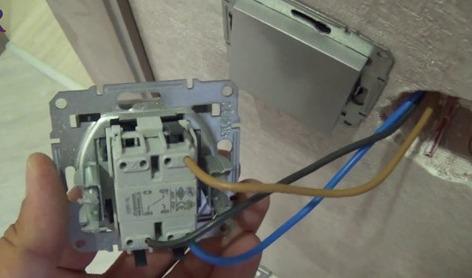
Then tighten the bolts of the expander petals until the device is fully fixed in the sub-socket and, if the design provides for it, fasten it to the wall with self-tapping screws.

After that, you can install back the plastic parts, apply voltage and test the operation of the circuit.
More detailed instructions on installing the switch are described a separate article.
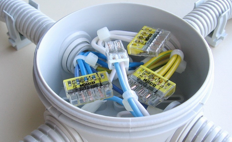
Connection using junction box
Connection in a junction box is always recommended, except for the case of light control circuits with several points, connected in series loop through and cross-over switches. In this case, it is better to make cabling and daisy-chain connection.
If the installation with junction box is selected, it is performed according to the following principles:
- From the switchboard to the box is laid a two-core supply cable (three-core, if there is a grounding conductor) with phase and neutral wires;
- To each luminaire a separate two-core cable is laid (three-core in TN-S networks TN-S or TN-C-S NETWORKS) with cores L и N (PE);
- conductors N и PE follow a transit through the box to the lamps, if necessary they are branched according to the number of luminaires;
- the phase conductor has a break, in it the switching device is connected according to the diagram;
- The cable with the corresponding number of conductors is lowered to the switch.
Conductor PE must be laid in the presence of protective grounding, even if luminaires are used without grounding (e.g. with incandescent lamps). This will help to avoid problems when reconstructing the network in the future.
It is recommended to see a visual representation of how this is done by craftsmen.
Connection of a switch with parallel light bulbs
There are no fundamental differences from the usual connection - the phase and neutral wires are pulled to the first lamp in the scheme, then a loop to the second and so on. If one lamp burns out the rest will remain in operation. It is only worth remembering that in such a scheme The switch must be designed for the total current of all lamps.

Read also: How to connect light bulbs in series and in parallel
Schematic examples of connection
As a simple example, let's look at what a circuit looks like of connecting a switch to a single light bulb (protective grounding in place). A three-core cable is led from the shield to the box and a three-core cable also goes to the light bulb. Phase wire is broken, in the gap with a two-core cable is included switching device.

Similar A scheme with a triple switch and three lights looks much more complicated. There are more connections in the box, so it is necessary to choose a larger size distribution box.

Even more complicated looks the installation in a box scheme with two lights and two double loop-through switches. Such a scheme is better to perform a daisy-chain.

Obviously, the second option simplifies installation and reduces cable consumption.

Mistakes and possible malfunctions
One of the main mistakes when wiring a switch is to misidentify the location of its terminals. Many people assume that by default a separately made terminal is always common. This is not the case - manufacturers can arrange the terminals in any order. Therefore it is necessary to identify the terminals of the device before starting the installation. This is easy to do if the device is marked with a diagram. If not, you can use a multimeter to check the internal connections. At the same time this process will be a test of the unit for serviceability.
Another common mistake is improper connection of conductors in the box. To minimize it, you should use cables with labeled strands. If the cores are single-colored, after laying and cutting the cables, you must call them out with a multimeter and mark them yourself.
Video lesson: 5 mistakes when wiring junction boxes.
Safety precautions
The basic safety precaution when installing wiring Do all work with the power off. If the lighting system is made from scratch, then the connection of the supply wire to the circuit breaker is performed last. If work is carried out on the reconstruction or repair of an existing circuit, technical measures must be taken:
- turn off the circuit breaker (or circuit breaker) of the lighting system;
- take measures to avoid spontaneous or erroneous switching on - disconnect the supply wire from the terminal of the circuit breaker;
- If the power supply system is based on the TN-S principle, the disconnected wire must be connected to the grounding rail;
- Check the absence of voltage on the phase wire.
Important! Check the absence of voltage must be checked directly at the place of work - in a distribution box or on the terminals of the switch.
Labor safety rules when working in electrical installations also prescribe the use of dielectric gloves, carpets, insulated power tools. It is unlikely that anyone in the home will have laboratory-tested protective equipment, but if possible, you should use it. There is never too much safety. At the very least, the insulation condition of the hand-held tool can be monitored visually. With this approach, the probability of electrocution during work will be minimal, the installation will be error-free, fast, and will last long and reliably.