How to connect a triple switch - wiring diagram
In addition to household switches are on sale devices with two and three buttons. The latter cause the greatest number of questions among buyers. In fact, such devices find use in the home and in office premises. It is possible to install and perform the connection of the triple switch yourself.
How a switch with three keys is arranged
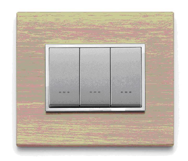
In appearance, the triple light switch looks like an ordinary light switch, but it has three moving panels. This determines the size of the device - in most cases, it is somewhat wider than the one- and two-key counterparts.
Each controls its own group of contacts to turn on and off independently of the others. When you manipulate the key, voltage is applied (and removed) to the allocated load.

If you remove the keys, the switch mechanism with 3 moving elements will open.

To install the switch at the mounting location, the decorative plastic frame will also need to be removed. Other switch designs, such as three-button switches, have a similar design.

After that, the following will be available:
- the screws of the expanding paddles;
- terminals to connect the wires;
- holes for attaching the device to the surface.
You can see that the device has a common contact at the top, but this is not always the case. This should be taken into account when preparing for installation.
Scope of application of the three-key switch
The most obvious use of a 3-panel device - separate control of three lighting devices. Such a need in the home - a rarity. But in offices or warehouses - quite a real situation.
But in the house or apartment can be used multi-arm chandeliers. Although they are real power eaters (two 50-watt incandescent bulbs give less luminous luminous fluxthan one hundred-watt bulb), such lighting fixtures are widely used for aesthetic reasons. You can increase the economy and comfort of use of such luminaires by using switches with multiple buttons. By controlling individual lamps or groups of lamps rather than the chandelier as a whole, you can choose a comfortable level of light and not waste energy.
Choice of installation location
If you refer to the seventh edition of the Rules for Electrical Installation, it turns out that there are no strict conditions for the installation of household switches. Section 7.1.51 recommends that switches should be installed at the entrance at a height of one meter on the handle side. The rules only determine the minimum distance to the gas pipes. It should not be less than 50 cm. But there are two exceptions:
- in children's institutions switches must be mounted at a height of 1.8 m - beyond the reach of children;
- It is forbidden to install switchgear in wet rooms (baths, baths, baths, showers).
Otherwise, when choosing where to install three-key devices can be guided by their own ideas about comfort and safety.

Wiring options
The obvious connection scheme of any three-key switch is to control three different lights. Each of the 3 contact groups switches a different luminaire independently of the others.

When connecting through a distribution box, the wiring topology looks like this:

From the figure you can see that to perform this installation will require:
- a three-core cable from the distribution board;
- three cables with three conductors to each consumer;
- four-core cable from the junction box to the switchgear.
There are many connections in the junction box. Therefore, it is necessary to choose an appropriate size switchboard.
Important! The PE conductor may not be present in TN-C power supply systems. It does not affect the function of the circuit. If it is present, however, it must be routed and connected to the terminals marked with the letters PE or the ground symbol. It is a matter of operational safety.
In the absence of a protective conductor, the number of cores in the supply and outgoing cables is reduced by one. A two-core cable will go in and out of the box to each consumer, but four conductors must be pulled to the switch in any case.
Another way to connect a device with three independent groups of contacts is to control multi-arm chandeliers.

The difference of this circuit from the previous one:
- The PE and N conductors are not pulled to each individual lamp, but to the chandelier as a whole;
- Each key can control either a single lamp or a group of lamps, depending on the internal circuitry of the chandelier.

If you study the scheme of laying conductors, it is obvious that in this case the installation in the distribution box will be much less dense than in the previous case. The second difference is the list of cables. If the lighting is fed from a TN-S or TN-C-S network (with protective conductor PE), then the wiring will require:
- 3-core cables from the switchboard to the box (two if there is no PE);
- A five-core cable from the switchboard to the chandelier.
As in the previous case, the switch is connected with a four-core cable.
The video shows the wiring diagram clearly by example.
What you need for installation
Perform electrical installation is not possible without a minimum set of tools:
- for stripping the insulation will need a mounter knife;
- To shorten the conductors, you will need wire cutters;
- To check the absence of voltage you will need a screwdriver indicator or a multimeter;
- For installation work - a set of screwdrivers.
If the connection in the distributor is made by twisting copper conductors, it is desirable to solder the joints. To do this you will need a soldering iron and supplies for it. Perhaps in the process of work there will be a need for other tools.
Preparatory Work
Before you begin assembling, determine where the switches will be installed. If you intend to do a concealed wiring, buy switches recessed and sub-sockets of appropriate size (plastic boxes, in which the device will be installed). For exposed wiring, you must put pads where the devices will be installed.
Cross section selection
The cross-sectional area of the cable depends on the load and the mode of installation. Many years of experience have shown that cross-sections in 1.5 sq.mm in terms of bandwidth and mechanical strength is sufficient for 99+ percent of of lighting applications. This size has become a definite standard. The widespread use of LED products only confirms this thesis - loads in lighting networks do not increase. But if the case is non-standard, you can choose a cable according to the table.
| Cross section of conductor, sq.mm | Allowed current, A | Permissible load at 220 V, W | ||
| Copper | Aluminium | Copper | Aluminium | |
| 1,5 | 19 | - | 4100 | - |
| 2,5 | 27 | 21 | 5900 | 4600 |
| 4 | 38 | 29 | 8300 | 6300 |
| 6 | 50 | 38 | 11000 | 8300 |
Although the rules allow the use of aluminum conductors, it is strongly recommended to use only copper products.
Next it is necessary to perform wiring - to lay cable products in accordance with the selected scheme between all the elements. It is better to use products with numbered and marked by the color of the insulation cores. If there is no such cable, you will have to perform wire-cutting and core marking yourself. Cables should have a small margin of 10-15 cm in length. Once this work is done, you can proceed with the actual installation.

Safety Requirements
When carrying out work, it is necessary to observe the main rule: all work is carried out on de-energized equipment. If the wiring is installed from scratch, the connection to the switchboard must be performed last.
If you are reconstructing an existing lighting system, you must for safety reasons
- Disconnect the appropriate circuit breaker in the switchboard, identifying it from the diagram or markings;
- create a visible break by disconnecting the wire from the circuit breaker terminal - this prevents the voltage from being erroneously applied;
- check that there is no voltage AT THE PLACE OF THE WORK IMMEDIATELY.
Use of insulated hand tools promotes safety. Make sure that the insulation of the handles is not damaged or worn.
Installing the Switch
Assembly of the circuit can begin with the installation of the switch. Wires, brought into the device sub-socket, should be shortened with wire cutters to a reasonable length - so you can put the unit in place. Next, remove the upper sheathing from the cable with a cable fitter's knife.

Then you should clean insulation of conductors with the same knife, if you have a wire stripper it will be more convenient to work with. As a result it should look like this:

Next, you need to look at which side of the common terminal is located. From this depends on what will be the on or off position of the switch.

In Russia, it is customary to have the "off" position with the lower edge of the button depressed. This tradition comes from the requirement that the switching element cannot be switched on by its own weight. This rather applies to switches, but the principle is well established. Another version is that the rule comes from the condition that in a critical situation a person should be able to turn off the tension by the action of his body gravity. In any case, it is a force of habit. Some countries have adopted the exact opposite standard, and it doesn't affect the actual operation of the lighting system.
Therefore, it is necessary to connect the switch so that it is convenient and habitual to control the light.

After that, you can install the device in the sub-socket, unfasten the petals, fasten with self-tapping screws to the wall and put the plastic decorative elements in place.

Installing the junction box
If three-connector is used to switch three independent consumers, each of which has its own cable, then arrange the conductors in a box must be so:

Connect the wires according to the diagram above:
- connect the PE conductors (yellow-green) with each other;
- connect the neutral conductors (white in this case, except for the one going to the switch) with each other as well;
- Connect the red wire of the supply cable to the red (to avoid confusion) of the switch, this will be the common conductor;
- the white, brown, yellow wires of the four-core cable connect to the corresponding red wire of the cables going to the lamps.
Of course, the color of the cores does not affect the performance of the system, but compliance with the order of colors will minimize installation errors and facilitate possible repair in the future.
If the three-key switch controls the individual lamps of a multi-arm chandelier, the installation looks less cumbersome.

As in the previous case, the yellow-green (PE) and white (N) wires must be connected between the supply cable and the chandelier outlet - they go through the box in transit. The red cores of the feeder cable and the outgoing cable to the switch are also connected. And the white, yellow and brown cores can be connected to the same color strands of the outgoing five-core cable.

Connect the conductors can be twisted, and then soldered (not necessarily, but desirable - in the future will reduce the likelihood of deterioration of the contact due to oxidation of copper). When the connection is completed, the stranding should be insulated.
Better yet, connect the cores with special terminals - preferably screw-type terminals. Clamp-type terminals are more convenient, but the reliability of such a contact is lower.


This video shows both a schematic diagram and how to connect the 3rd circuit breaker to the mains.
Typical errors
Installation errors can be due to improper connection of conductors. But the use of cables with marked cores, compliance with safety measures and care during installation should reduce the likelihood of such errors to zero. Then the lighting system will last for many years, bringing only a sense of comfort.