Design and wiring diagram of a pass-through dimmer
The market for household appliances provides consumers with a wide range of equipment that allows them to arrange a lighting system for comfortable use, as well as an opportunity to save on electricity bills. New products are constantly being offered for sale, and it is not easy to immediately understand the use of which without being a professional. The subject of this review is a device that combines the capabilities of a dimmer with the functions of a pass-through switch. It is called a pass-through dimmer.
What is a pass-through dimmer
In some cases, there is a need to turn on and off lights from two or more points independently. The scheme for such a case is known, for 2 places it is implemented on ... two loop-through switches.... If you need more, you need to add the required number of cross-switches.

If you need to smoothly regulate the level of light, it is easy to supplement this scheme with a dimmer - device for continuously adjusting the level of illumination. The dimmer must be connected in the gap of the phase wire, and it does not matter whether it is before the first or after the second light switch.
Dimmers are usually equipped with power switches, so they can be assigned the functions of the main control. From the remote control you can not only adjust the brightness, but also turn off the light mains voltage, regardless of the position of the other switches (unfortunately, you can not turn it on independently). The disadvantage of this scheme is the need to install an additional device, the associated arrangement of a socket, finding space for this.
Therefore, it is often more advantageous to use a combined device - dimmer+through switch.

It combines the functions of the two devices:
- allows you to adjust the brightness of the light;
- has a change-over contact group that allows the unit to be used as a through-type switch.
Therefore, a certain amount of economy is achieved when using it, but The control function of the central panel is lost.
Advantages and disadvantages of the pass-through device
Equipping the dimmer with a special contact group does not fundamentally change its properties, so the pass-through dimmer has all the pros and cons that the usual one. Its main advantages are:
- the possibility of saving electricity;
- Extension of service life of incandescent bulbs due to the smooth heating of the filament.
The main disadvantage is the emergence in some modes of strobe effect, which does not allow you to visually adequately assess the status of rotating mechanisms.
The principle of operation and structure of the regulator
Dimmers come in different designs, and the most popular is a rotary. But in a control scheme with two through-line switches such a dimmer is not suitable - it switches only in the position of minimum brightness. Therefore, to organize such a control scheme, other types of light controller actuators are used:
- rotary-push (switches in any position of brightness);
- controlled remotely (by remote control);
- push-button (with more or less buttons and a separate key for switching);
- touch, as well as other types of dimmers.
The basic principle is the same - brightness adjustment and contact control are performed independently.
The internal block diagram of the dimmer looks like this:

The control circuit is usually based on a trinistor or triac. The average current is changed by cutting off part of the half-period of alternating voltage.

If the light controller is built according to a similar circuit, it does not matter whether the dimmer is placed on the supply side or the load side. It does not affect the operation of the circuit. For other circuits this point must be studied individually.
But it does not make sense to install dimmers on both sides at once: they will try to "slice" a sinusoid on their own, the brightness will be regulated unpredictably. With this scheme, one of the devices can be used only for switching, permanently setting it to the position of maximum brightness. But from an economic point of view this is wrong - It is cheaper to buy a switch with changeover contacts.
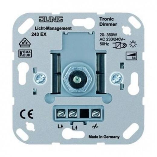
The outputs of the device are connected to external terminals that are labeled destination.
Important! Alphabetic marking of symbols is not standardized. Manufacturers may apply other designations to the external terminals as well. In many cases, a stylized diagram is applied to the switch instead of the switch symbols.
It is almost impossible to find a cross dimmer on sale. If someone makes such devices, the circuit will be cumbersome, unreliable. After all, the brightness must be adjusted synchronously on two channels at once. That's why the best scheme would be one continuous dimmer, one continuous loop-through switch and the required number of cross switches.
Materials and tools for installation
If the wiring and installation locations of switching devices are already done, you will need a minimum list of tools:
- a fitting knife (it can be used to remove the insulation);
- screwdriver set (for partial disassembly, assembly and fastening of devices);
- wire cutters (for shortening wires)
- screwdriver indicator and/or multimeter (for checking the absence of voltage and checking the correctness of installation).
If the wiring is made with copper cable (it is recommended to do so) and it will be installed in the distribution box by twisting, then the joints must be soldered. To do this you will need a 40-60 watt soldering iron with a set of consumables. You will need electrical tape or caps to isolate the stranded connections. If you have chosen to use terminals (screw and spring-type), then you will need to purchase a terminal kit.


If there is no wiring, you will need additional tools for its arrangement. Their set depends on the intended method of installation. For open wiring will need trays, brackets or racks and a drill (hammer) for installation. For closed - a tool for making strokes (strobot cutter, perforator, in extreme cases, a chisel with a hammer) and a drill with a drill bit for making hollows.
Wiring diagrams
A dimmer with a flip-flop contact group is connected in the same way as a normal feed-through switch, regardless of the type of action on the contact group. Two variants are possible.
With the use of a junction box
You can mount the passage dimmer by the classical method - with the use of a junction box. This installation looks more professional, in the box, if necessary, it is not difficult to make switches or partial diagnosis of wiring by testing the individual conductors.

But in this case you have to assemble a large number of connections in one box, this complicates the installation and increases the chance of errors. These disadvantages are only exacerbated when the circuit is made more complicated - by adding cross switches or the use of two-way two-way devices.

Looping
It is obvious from the previous drawings that the conductors connecting the loop-through and crossover switchgear do not need to be brought into the box. They can be routed over the shortest possible distance. Such a wiring diagram of the loop-through dimmer allows you to mount the lighting system without the junction box. Connection of the elements is performed in series - daisy-chain.

N and PE conductors can be run directly to the lamp, or you can lay in transit along with the phase. The phase conductor in either case is fed to the first loop-through unit, daisy chained to the second, and then the supply conductor goes to the lighting fixture.

This type of laying does not have the problems inherent to installation with the use of a distribution box. Another important advantage of loop-through wiring is that you will save a lot of money on cabling.
We recommend that you take a look.
Important points to consider
Unlike a conventional loop-through switch, a dimmer with a flip-flop contact group may not work with all types of lighting fixtures. This is due to the peculiarities of the principle of the lamps. Before installing (or even better - before buying) dimmer you need to find out what area the device is used for. You can do this by marking the device or by studying the technical data sheet.
| Alphabetic designation | Symbol designation | Type of load | Permissible load type |
|---|---|---|---|
| R | Active (ohmic) | Incandescent lamps | |
| L | Inductive | Voltage transformers for low-voltage lamps | |
| C | Capacitive | Electronic transformers (voltage transformers) |
There are also universal devices, their marking contains several letters (e.g. RL). There are also universal models, they can be connected to the network with any type of lamp, including LED lamps. But the lamps themselves must be marked with the Dimmable label or a corresponding pictogram.

Diagram of connection of dimmer from the usual circuit of the switch does not have a fundamental difference. But the nuances still exist, before developing a lighting system, it is better to study them. With a conscious approach to the organization of the network, it will last a long time and will deliver only a feeling of comfort. If this is not done, you can incur unforeseen losses of money and time.