Description of COB LEDs
Not so long ago, the market began to fill the LED-lights, made by COB technology. Immediately after the appearance of such products, information about them began to acquire the character of myths. This review - an attempt to separate the truth from fiction and tricks of marketers.
What is a COB LED
Ever since the appearance of SMD-LEDs, engineering thought did not stand still. The developers of many manufacturers have solved the problem of reducing the size of lighting equipment, increasing the light output, simplifying and reducing the cost of mounting technology, assembly, etc. Now it is difficult to establish who was the first to come up with the idea not to enclose each p-n junction in a separate body coated with phosphor, but to put several arsenide gallium crystals in a single shell. But the first sample of such a product appeared on the market in 2003 from Citizen Electronics.
The idea turned out to be a breakthrough. In addition to solving the problems mentioned above, it was possible to concentrate the radiating elements in a relatively small area and obtain less light scattering. This technology is called COB - chip-on-board. Perhaps a more accurate translation would be "element on a board" or "crystal on a board.

For a long time, the release of matrices made according to this principle was held back by the complexity of gluing LEDs to the substrate. The thickness of the glue must be strictly calibrated: a decrease in the layer leads to a decrease in the strength of the attachment, while an increase leads to a decrease in the efficiency of heat dissipation. In 2009 this problem was solved and COB-technology began its triumphal march in the world of lighting technology.
The module produced using this principle contains a matrix of LEDs without housings, placed on the base. Due to the absence of shells it was possible to increase the density of the radiating elements and increase the brightness per unit surface. In some cases the LEDs are encapsulated in a transparent compound for strength. The upper part of the shell is coated with a phosphor.

The printed circuit board is made using conventional technology, consisting of conductive tracks arranged on a dielectric substrate. A plate of metal with high thermal conductivity is glued to the bottom, and the product gets a finished look.
Important! In most cases, the regular radiator is not enough to provide a normal operating temperature of the LEDs. It is necessary to use an additional external heat sink.
Typical values of luminous flux of matrixes with 0,762 * 0,762 mm crystal size depending on the power are presented in the table below.
| Electric power, W | Number of elements, pcs. | Luminous flux, lm |
| 10 | 9 | 450-550 |
| 30 | 30 | 1800-2200 |
| 50 | 50 | 2550-2750 |
| 100 | 100 | 4500-5500 |
Actual parameters may vary slightly due to additional conditions.
Types
Recently, COB-LEDs with built-in drivers have appeared on the market. "On board" now not only the matrix, but also rectifier elements, as well as a chip to stabilize the current through the emitting elements. As you can see, the additional elements are not hidden under a common casing, but mounted on a separate board and combined into a module.
This type of LED technology COB is a single unit, to which the only thing left is to bring the supply voltage.
Operating principle and characteristics
No new principles are laid down in the basis of COB-LEDs. Same p-n junction of gallium arsenide, indium phosphide or other materials. Same basic charge recombination with emission of a light quantum when a direct voltage is applied. The same monochromatic light with a narrow spectrum. The same principles of obtaining inaccessible colors - when power is applied, the emission of LEDs (in the optical range or UV) initiates the luminescence of the phosphor. This well-known method allows you to get colors that can not be achieved by direct glow semiconductor transitions. Also the problem of heat dissipation has not disappeared. The novelty of the elements - only in the technology of production, which allows you to bring the light-emitting devices to a new consumer level.
Control
Control of COB-LEDs is reduced to switching the supply voltage, and in this respect there is no fundamental difference from conventional devices. Such an element can be switched on and off:
- a manual switch for the appropriate voltage;
- electromagnetic relay or starter;
- electronic switch (transistor, thyristor).
It is only necessary to take into account that the power of such a LED can be up to 100 W, and the operating voltage - 220 V. The switching element must have the appropriate parameters.
Recommended for viewing: COB led vs smd led
Pros and cons
Important! Given the cheapness of COB LED production, these disadvantages are gradually losing importance. It's becoming more economical to replace the matrix rather than rebuild it.
Manufacturers' declarations of higher light output relative to the power due to the new principles of production, most likely, should be attributed to marketing tricks. It has already been noted that the new principles of COB matrices are not laid down. And some increase in luminous efficacy can be connected with natural development of technologies of production of phosphors and semiconductor crystals.
Lifetime
COB matrix manufacturers claim an average life of about 30,000 hours. This is about 3.5 years of continuous operation. With conventional LEDs in the specifications this period is usually stated in the range up to 50,000 hours (5.5 years). It is often concluded that the reliability of COB elements is low. In fact, the experience of operating new light-emitting devices has not yet been accumulated. All figures are derived from calculations, which often do not take into account operating conditions. And it is unlikely that any manufacturer has carried out real life tests lasting several years. There is no point in them - new technologies and materials will come during this time.
It should be taken into account that the warranty periods for both elements are set approximately the same - around 15,000 hours. Anything beyond that is predictions and pure marketing. Therefore, all information about service life to date are declarations and should be treated with caution.
LED lamp on COB-LEDs
Another advantage of the new technology - it is possible to produce matrices of any shape and size. In most cases, devices are produced round and rectangular (square), from which you can make lamps of different configurations.

The "corn" lamp, which got its name because of the discrete elements resembling grains of the crop, got a new look. Now there are no glowing dots, the surface has become solid and the radiation is more uniform. The size of such lamps is now limited by the requirements of the mechanical strength of the matrix, but it is hoped that the development of technology in the near future will bypass this problem.

LED illuminator using such matrices can have either one radiating element or several - depending on the required brightness of luminescence. A single matrix, replacing several smaller ones, is not yet equipped with luminaires because of the mentioned size limitations.
Wiring diagram
Wiring diagram depends on the design of the matrix. If it's just a parallel chain of elements, then include them in a domestic single-phase 220 V network should be through a rectifier or driver for the appropriate voltage and current, just like the usual single LEDs or assemblies.

If the rectifier and driver are "on board", the connection is no different from a normal incandescent lamp. Already mentioned "corn", for example, has a standard socket for screwing into the socket.
Pinout
LED, like a conventional diode, is a device that conducts current in one direction. Therefore, the polarity must be observed when wiring. The anode must be connected to the plus terminal of the power supply, the cathode to the minus terminal.

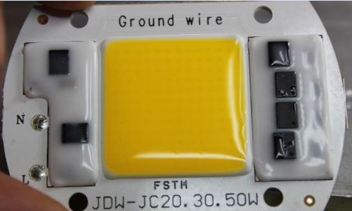
It is easy to locate the COB matrix pins - the markings are printed directly on the housing. The pins are marked with "+" and "-". If the assembly can be plugged directly into an AC voltage circuit, the pins are marked L (phase) and N (zero).
There is an opinion that lighting elements produced by COB-technology will soon completely displace SMD-LEDs. In fact, it is unlikely to happen. After all, SMD elements have not completely replaced the pins, although they have significantly squeezed them out. Most likely it will be the same situation here - each technology will take its niche.