Connecting an LED to 220V
LEDs as light sources are widely used. But they are designed for low voltage supply, and often there is a need to turn on the LED in the domestic network of 220 volts. With a little knowledge in electrical engineering and the ability to perform simple calculations it is possible.
Ways to connect
Standard operating conditions for most LEDs - voltage of 1.5-3.5 V and a current of 10-30 mA. When you directly plug a device into a household power grid, its lifetime will be a tenth of a second. All the problems of connecting the LEDs in the network increased compared to normal operating voltage, reduced to repay the excess voltage and limit the current flowing through the light-emitting element. Drivers - electronic circuits - cope with this task, but they are quite complex and consist of a large number of components. Their use makes sense when powering a LED matrix with many LEDs. There are simpler ways to connect a single element.
Connection with a resistor
The most obvious way is to connect a resistor in series with the LED. This resistor will carry the extra voltage and limit the current.

Calculation of this resistor is done in this sequence:
- Suppose there is a LED with a rated current of 20 mA and a voltage drop of 3 V (the actual parameters should be consulted in the reference book). For the operating current it is better to take 80% of the nominal - LED in lightened conditions will live longer. Irab=0.8 Inom=16 mA.
- On the additional resistor will be the voltage drop in the supply line minus the voltage drop on the LED. Urab=310-3=307 V. It is clear that almost all of the voltage will be in the resistor.
Important! When calculating you should not use the effective mains voltage (220V) but the peak voltage of 310V.
- The value of the added resistance is determined by Ohm's law: R=Urab/Irab. Since the current is chosen in milliamps, the resistance will be in kiloohms: R=307/16= 19.1875. The closest value from the standard range is 20 kOhm.
- To find the power of the resistor using the formula P=UI, you must multiply the operating current by the voltage drop across the quenching resistor. With a 20kOhm rating, the average current will be 220V/20kOhms=11mA (you can take the rms voltage into account here!), and the power will be 220V*11mA=2420mW or 2.42W. From the standard range you can choose a 3W resistor.
Important! This calculation is simplified, it does not take into account the voltage drop across the LED and its resistance in the open state, but for practical purposes, the accuracy is sufficient.

You can connect a chain of LEDs in series. When calculating, multiply the voltage drop of one element by the total number of elements.
Series connection of a diode with high reverse voltage (400 V or more)
This method has a significant disadvantage. The LEDlike any device based on p-n junction, transmits current (and glows) at the forward half-wave of alternating current. In the reverse half-wave it is locked. Its resistance is high, much higher than the ballast resistance. And the mains voltage of 310V amplitude applied to the circuit will fall mostly on the LED. And it is not designed to work as a high-voltage rectifier, and can fail pretty soon. To combat this phenomenon, it is often recommended to include an additional diode in series to withstand the reverse voltage.
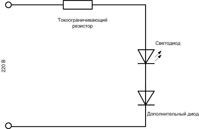
In fact, with this inclusion, the applied reverse voltage will split roughly in half between the diodes, and the LED will be slightly lighter at a drop of about 150 V or slightly less, but its fate will still be unfortunate.
Shunting the LED with an ordinary diode
This circuit is much more effective:

Here the light-emitting element is switched in opposition and parallel to the additional diode. At the negative half-wave the additional diode will open and all voltage will be applied to the resistor. If the calculation made earlier was correct, the resistor will not overheat.
Parallel connection of two LEDs
When you study the previous circuit, you can't help but think - why use a useless diode when you can replace it with the same light emitter? This is correct reasoning. And logically the circuit is reborn in the next version:

Here the same LED is used as a protective element. It protects the first element during the reverse half-wave and in doing so it radiates. At the right half-wave of the sine wave the LEDs swap roles. The plus side of the circuit is the full utilization of the power supply. Instead of single elements, chains of LEDs can be included in the forward and reverse directions. The same principle can be used to calculate, but the voltage drop on the LEDs is multiplied by the number of LEDs installed in one direction.
Using a capacitor
A capacitor can be used instead of a resistor. In an AC circuit it behaves somewhat like a resistor. Its resistance depends on the frequency, but in a domestic circuit this parameter is constant. You can take the formula X=1/(2*3.14*f*C) to calculate, where:
- X is the reactance of the capacitor;
- f - frequency in hertz, in our case it is 50;
- C - capacitance of capacitor in farads, for conversion into μF use coefficient 10-6.
In practice, the formula is used:
C=4,45*Irab/(U-Ud), where:
- C - required capacitance in μF;
- Irab - operating current of LED;
- U-Ud - the difference between the supply voltage and the voltage drop across the light-emitting element - is of practical importance when using a chain of LEDs. If one LED is used, the U-value can be assumed to be 310 V with sufficient accuracy.
Capacitors can be used with an operating voltage of at least 400 V. Calculation values for currents that are typical for such circuits are given in the table:
| Operating current, mA | 10 | 15 | 20 | 25 |
| Capacitance of ballast capacitor, uF | 0,144 | 0,215 | 0,287 | 0,359 |
The resulting values are quite far from the standard series of capacitance. So, for a current of 20 mA, the deviation from 0.25 uF is 13%, and from 0.33 uF is 14%. The resistor can be chosen much more accurately. This is the first disadvantage of the circuit. The second has already been mentioned - capacitors at 400 V and above have quite large dimensions. And that's not all. When using a ballast capacitor the circuit is overgrown with additional elements:

The resistance R1 is set for safety reasons. If the circuit is powered from 220 V and then disconnected from the mains, the capacitor will not discharge - without this resistor there will be no discharge current circuit. If you accidentally touch the terminals of the capacitor, it is easy to get an electric shock. The resistance of this resistor can be chosen as a few hundred kilohms, in working condition it is shunted by the capacitance and does not affect the circuit operation.
Resistor R2 is needed to limit the inrush of the charging current of the capacitor. While the capacitor is not charged it will not serve as a current limiter and during this time the LED may have time to fail. Here you should choose the value of a few dozens of ohms, it will not have any effect on the circuit performance either, though it can be taken into account in the calculation.
Example of incorporating an LED in a light switch
One common example of the practical use of an LED in a 220 V circuit is to indicate the off state of a household switch and make it easier to find its location in the dark. The LED here operates at a current of about 1 mA - the glow will not be bright, but will be noticeable in the dark.

Here the lamp serves as an additional current limiter when the switch is open, and will take a small fraction of the reverse voltage. But the bulk of the reverse voltage is applied to the resistor, so the LED here is relatively protected.
Video: WHY DO NOT install a lighted switch
Safety Engineering
Safety at work in existing installations is governed by safety regulations for the operation of electrical installations. They do not apply to the home workshop, but their basic principles should be taken into account when connecting the LED to the 220 V mains. The main rule of safety when working with any electrical installation - all work must be carried out with the voltage off, excluding erroneous or unintentional, unauthorized activation. After disconnecting the circuit breaker, the absence of voltage must be check with a tester. Everything else - the use of dielectric gloves, mats, imposition of temporary grounding, etc. is difficult to implement in the home, but we must remember that safety measures are not enough.