How to check if the LED is working properly
LEDs - LEDs are semiconductor devices for artificial light. Their operation is based on the emission of light photons and electromagnetic energy in the visible, infrared and ultraviolet frequency range. Light is emitted by the p-n junction in the contact area of p- and n-type diodes during the constant stabilized current flowing through it. This radiates light (about 6 - 15% of the consumed power) and releases heat - at least 80 - 90% of this energy.
Main causes of diode failure
There may be several causes of failure. Testing is done according to a special technique. The main causes of failure:
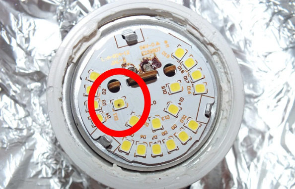
- Thermal breakdown due to overheating and destruction (breakdown) of the crystal. Accompanied by burning of the lacquer coating and plastic housing. The photo shows a burnt-out LED on the circuit board of a retrofit lamp, an analog of a MR16 type halogen lamp. In one of the housings SMD2835 The yellow phosphor on the crystal burned out due to overheating. You can see the brown dot on the element with the position designation D11.
- Electrical breakdown of p-n junction. Direct operating voltage of a diode, depending on glow color and p-n junction materials, ranges from 1.5 to 4-4.5 V. The reverse voltage is several volts higher than the forward voltage. Therefore, voltage spikes can cause instability in the output. If they exceed the reverse voltage of the diode, a breakdown may occur.
- Mechanical breakdown. Silver or gold wires are supplied with current to the semiconductor crystal from the body contacts. Vibration or shock can cause them to break.
- Degradation. Gradual degradation of LED characteristics, especially brightness and glow tint. The drop in brightness is normalized at 30, 50 and 70% of the original. At 5-10% brightness drop in the first 1000 hours of most devices. A brightness drop of 50-70% requires replacing the lamp, module, strip or ribbon. Sometimes it occurs in 15 to 20 thousand hours.
Recommended: Checking an LED lamp with a multimeter
Degradation occurs in the phosphors of white LEDs and in the elements of secondary optics - lenses built into the housing or mounted on its surface. Under the influence of light, the lenses become turbid, reducing light transmission and luminous flux.
"LED diode wire-checking with a multimeter, diode wire-checking" is a slang term that got into lighting engineering from electrical engineering of low currents. When it was necessary, for example, to check the serviceability of conductors in the cable, you took a battery, battery or a portable power supply and an ordinary electromechanical bell. The battery and the bell were connected to the first contact of the cable connector with a crocodile. At the back end of the cable, the other wires were connected in series to the first wire. The ringing of the bell showed the serviceability of the wires.
The same way we checked if the wires in the cable were shorted to each other. The method was also used after checking the bell with an ammeter. The name of the operation was fixed by electricians and then passed to electronics. Only not a bell was used, but a tester, which was called differently - AVO meter, ohmmeter, multimeter.
You can check if the LED is working properly with a multimeter directly on the board or by unsoldering it. The device is used to test DC and AC circuits. It measures voltage, resistance of resistors in ohmmeter mode, the serviceability and efficiency of capacitors, rectifier diodes, p-n-p and n-p-n transistors and other.
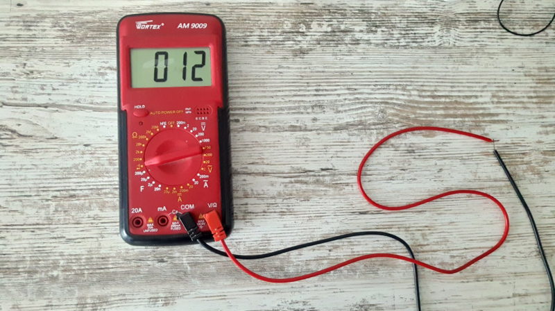
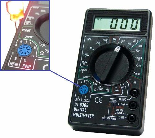
The red probe and wire of the multimeter are the positive pole or "+" circuit of the power supply and the anode of the diode. The black wire and stylus are the circuit connected to the cathode and negative pole of the source. The multimeter is switched to the DC measurement mode in the range of 0 to 20 mA or 0.02 A. The multimeter display shows 15.7 mA, which means that the diode is open and its operating current is the specified value. A LED of normal brightness at this current should glow and be slightly warm.
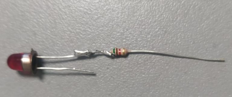
In the diode diagram the cross dash is the cathode and the triangle is the anode. The blue rectangle represents a constant resistance resistor. It limits the direct, i.e. operating current of the LED.
If the voltage is applied directly without current limiting, the operating value may be exceeded and the diode may break down thermally.
Checking LED's using a battery
To test the LED with a battery, you need to assemble the circuit according to the circuit diagram.
In the schematic:
- LED1 - device under test.
- 9V - power supply (9V battery).
- VAΩ - meter for measuring V - voltage, A - current, Ω - resistance, AVO meter or multimeter. In the schematic it works in voltage measurement mode.
- R1 - current limiting resistor.
- R2 - is a variable resistor that sets the brightness of the LED.
With the resistor R2 the nominal operating current is set on the multimeter. The faulty LED element gives light. A faulty one does not give any light.
The term "multimeter" is a transliteration of the international name "Multimeter". Formed from the terms "Multi" - many and "meter" - to measure. It has names "tester", "AVO meter" - from Amp-Volt-Ohm meter.
Modern multimeter - a universal measuring instrument with a digital display.
Another name of the device is "tester" - transliteration of the international term tester in Cyrillic - tester, checker, tester.
How to test without unsoldering
To test a LED without unsoldering it, you need to analyze the circuit of the device. If there are no circuits parallel to the diode, you can test it without unsoldering it. Parallel circuits can influence the result.
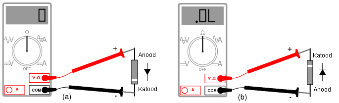
Sharp steel needles should be soldered onto the stylus of the multimeter. All the needle except the tip and the probe should be insulated, for example, with heat shrink tubing. The stylus with the needle pierce the layer of protective varnish up to the contact with the lead of the diode on the case or the contact pad on the board. Measuring the resistance in the forward and reverse direction shows the operability of the device. Forward resistance is tens to hundreds of ohms. Reverse resistance is hundreds of kilo ohms or more.
Checking SMD Diodes in a Flashlight
This is only done if the flashlight you can remove the board with the SMD diodeThe test is done without breaking it, and if there is a spare board with the same diode. Check by replacing the board with a known good board.
Video
For clarity we recommend a series of videos.
The wire-cutting in the bulb.
With a tester.
When there is no special device.
CMD device can be checked in different ways. The easiest and most accessible is to check with a multimeter. Allows you to check the diode without unsoldering it. Choose the method that is convenient for you.