How to wire a switch with a backlight indicator
Light switches with backlighting have long been part of everyday life. It is somewhat more convenient than the usual one - it is easy to find in the apartment in the dark, serves as an indicator of the light turning on, and in some cases its glow indicates the serviceability of the lamp. This device works independently of the knowledge of it, without additional interventions, but to understand the principle of operation is necessary. For example, in order to consciously solve problems that arise.
The device of the switch with backlight
In most cases, the backlight circuit is arranged in the same way and consists of:
- The ballast (damping element) - a resistor or capacitor;
- light-emitting element - LED (most often) or neon bulb.
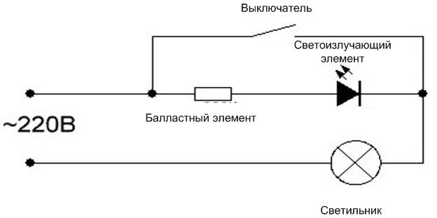
The chain elements are connected in series in series and connected in parallel to the contacts of the light switch.

When the switch is open, the current flows along the path "ballast - light-emitting element - luminaire". The damping element is chosen so that the current in the circuit is enough to ignite the indication, but not enough to light the main lamp. If the switch is closed, its contacts shunt the backlight circuit, the current goes along the path "contact group - lamp", its power is enough to ignite the light bulb.

Most often such a scheme is assembled on the basis of a light-emitting diode, but it has a drawback. During the reverse half-wave of the sinusoidal voltage, the LED is locked, its resistance is high. The mains voltage is divided between the lamp, the LED and the ballast in proportion to its resistance, and a large reverse voltage is applied to the LED. It is not designed for it, and its life is shortened - after a relatively in a relatively short period of time the LED will break down. To combat this effect in parallel LEDs are put in parallel with a normal diode in the opposite direction. During the reverse half-wave it opens and the voltage is shared most of the time between the main lamp and the ballast. You can put a second LED instead of a normal diode and increase the brightness of the light.
With ballast capacitor
A capacitor can be used as a damping element. In AC circuits, capacitance behaves like a resistance, and the rating depends on frequency (the higher the frequency, the lower the capacitance) and on capacitance (the higher the capacitance, the lower the resistance).

The fundamental difference from the resistor is that no active power is dissipated on the capacitance, so we can talk about a certain saving of electricity. How noticeable the savings with this technical solution can be determined by calculations. Let the quenching resistor resistor in the lighting circuit has a resistance of 220 kOhm (the resistance of the LED and the cold filament of the lamp in the preliminary calculation can be neglected). So the current through the resistor will be 1 mA, and 220 milliwatts of power will be dissipated on it. In one hour, the power consumption for the lighting will be 220 milliwatt-hours. Let the lighting be off for 20 hours per day. Then the cost of electricity for different periods can be summarized in the table.
| Period | Electricity consumption | Cost per kilowatt hour for households (average), $*kWh | Electricity costs per period,$ |
|---|---|---|---|
| Days | 4400 mWh=0.0044 kWh | 3,5 | less than a penny |
| Month | 132,000 milliwatt-hours=0.0132 kWh | 0,05 | |
| Year | 1584000 milliwatt-hours=0.1584 kWh | 0,55 |
Using a capacitor instead of a resistor saves a corresponding amount. The amount and value of the profit each consumer evaluates for himself. But it should be borne in mind that for this money he gets an increase in dimensions (the capacitor for voltage from 400 volts is quite large in size) and the need (in this case - the desirability) of an additional resistor in parallel with the capacity for its rapid discharge. In such circuits also put a resistor that limits the primary charge current of the capacitor, but in such a scheme its role is played by the lighting device.
With a neon bulb
As a light-emitting element can be used neon lamp.

It operates at even lower currents - from 0.2 A. The advantages of this light-emitting element:
- is not afraid of reverse voltage, you can not install additional parts;
- Lower current - less power dissipated at the ballast, smaller size, less heating.
The reduced current also reduces the likelihood of of LED lamps flashing when the switch is off.
Installation and connection of switchgear with illumination
The indication circuit has almost no effect on the operation of the switch, and for its functioning it does not matter on which side the phase wire will be approached. Therefore, for standard key devices, the presence of backlighting does not change anything. The device is also mounted in the gap of the phase wire. It also connects the supply wire, and departing conductors according to the number of loads. But there are a few points.
Installation of switches with one button
Installation and Single-key devices has no special features. But it should be taken into account that the indicator can be located both at the top of the panel of the device, and at the bottom (sometimes in the middle). Therefore, it does not make sense to focus on the position of the lamp in order to determine the enabled position of the keys.


Peculiarities of connection of the device with two keys
When When connecting a two-way When connecting a backlit two-key light switch, you should keep in mind that in most cases only one pair of contacts is equipped with an indication. Therefore, if you turn on one of the keys, the light-emitting element will go out and the device will remain without indication. This does not matter if the device switches two lighting systems in one room. But it can make a difference if the switch controls the light of two different rooms (toilet and bathroom in a separate bathroom).

Connecting a loop-through switch with an indicator circuit
For loop-through appliance the described principle of de-energizing the circuit is of little use. If the light circuit is open, the contacts of one switch may be closed. And if the light is set to only one pair of contacts (like a two-key switch), that circuit will be bypassed when the light is off.

To eliminate this disadvantage it is necessary to put illuminating elements on each pair of contacts and use two light emitters. This requires additional space inside the device and design refinements on the design of the front panel. Therefore, parallel schemes of inclusion of the emitting elements are used for marching switches.

In the first scheme, additional elements are connected in parallel to the fixed contacts. In this case, when the circuit is open and the lights are extinguished, both lights will be on. When the main circuit is assembled, both lights will be unpowered.

Another option is the power-on indication. In this case, the indicator lights are on when the light is on. The disadvantages of such a connection are:
- The need to lay a third wire between the marching switches;
- the need to lay a neutral N wire to the switches.
And the practicality of indicating the state of the luminaires on is questionable. These indicators will glow even if there is no lamp installed in the luminaire or the cable is forgotten to be connected to it.
See the visual connection of wires.
Disconnecting the indication circuit
If necessary, the elements of the backlight can be removed. Such a need may arise, for example, if LED or LED or energy-saving lampscaused by a small current flowing through a limiting element. This problem can be solved in other ways, but it may happen that removing the display is the only way out. In this case, you will need small wire cutters.
The work of removing the indication chain can be done on the disassembled device, or you can not dismantle the switch with the LED, just remove the decorative plastic parts. In any case, before starting work, you must disconnect the power supply to the lighting network by means of a switchgear in the switchboard. After that, make sure that there is no voltage directly on the switch.
After gaining access to the interior of the device, it is sufficient to cut off any lead of the LED. This will open the indication circuit. But it is better to completely remove the LED or neon to avoid accidental shorting by the cut pins.

It may not be enough to remove the plastic parts to gain access to the backlight chain. In this option, you'll need to continue disassembly of appliance. In most cases, this will not do without removing the switch from its place of installation.
The video is very quick to remove the LED from the switch.
Backlit switch with his own hands
Backlight circuit can be assembled and installed by yourself. This is especially true for old-style switches - they have no illuminating chains, but there is enough space inside to place the elements and enough space on the front to install a light bulb. On modern switches there is the problem of finding a place to install the light emitter, so in many cases it is easier to buy the appropriate unit. But it can be difficult to buy, for example, a three-key switch with a light emitter. Or you need a double switch with an indicator for each pair of contacts. So the lighting circuit will have to make it yourself.

Basically, the problem of creating a light chain comes down to the choice of circuit, calculation and selection of the ballast.
If a circuit with a quenching resistor is chosen, it is calculated as follows:
- The voltage drop across the ballast is determined Ubal=Ugrid-Ulamp. At the open LED will not drop more than 3 volts, so for practical calculations we can assume that the entire line voltage will be applied to the resistor Ubal = 310 volts (you should take the amplitude value, not the effective value of 220 volts). For a neon lamp, you should be guided by the ignition voltage, and it is tens to hundreds of volts. If you do not know this parameter for a particular lamp, you should set the voltage to 150 volts and the extinguishing element will drop Ubal=310-150=160 volts.
- Select the operating current of the radiating element. For LED it is possible to choose Irab=1...3 mAfor LED, for neon - Irab=0.5...1 mA.
- Resistance of the ballast will be equal to Rbal=Ugrid/Irab. If the current is in milliamps, the resistance will be in kiloohms.
- The power of the ballast resistor is Rbal=Ubal*Irab .. If no additional diode is used in the circuit, the value can be divided by two.
If a capacitor is selected as a voltage damping element, then the calculation is done according to the formula C=4,45*Irab/(U-Ud)where:
- С - required capacitance in μF;
- Irab - operating current of LED;
- U-Ud - is the difference between the supply voltage and the voltage drop across the light-emitting element (ignition voltage of the neon lamp).
The nearest standard capacitor rating is selected. It is desirable to round down, but make sure that the operating current does not decrease too much. As a diode, you can use any semiconductor device) for a reverse voltage of at least 400 V (current is not decisive). It is possible to choose a diode with appropriate dimensions from the following series 1N400X.
Next, it is necessary to drill a hole in the chosen place of the switch panel, glue the light element, assemble the chain of indication, connect it to the terminals of the switching device. After that, you can connect the switch with the installed indicator in place and test the operation of the backlight.