How to connect lights through a switch - wiring diagrams
The household light switch has long been a familiar appliance in the home and in industry. In addition to its direct function of closing and opening the electrical circuit, it often has a decorative and service load. To get the most comfort using the possibilities of modern devices, it is necessary to understand their varieties and areas of application.
What is a Switch
A switch is a household electrical appliance whose purpose is to apply voltage to light bulbs and turn them off. The average consumer does not think about its internal structure, although it is quite simple. Each key operates a movable contact which, together with the fixed contact, closes or opens an electrical circuit. Plus the terminals to which the electrical wires are attached, plus the decorative parts. This is the household electrical switch.

It is installed most often on the wall. The place of installation is regulated by the Rules for Electrical Installations. It is forbidden to install switches closer than 50 cm from the gas pipes, as well as in wet areas (bathrooms, showers, etc.).. In children's institutions switches are placed at a height of at least 180 cm. Otherwise, the rules only recommend installing appliances for switching at the entrance to the room at the side of the door handle at a height of 1 meter.
Types of electrical appliances
Although the task of any switch is to close and open an electrical circuit by controlling lights, there are many varieties of household switching devices. They can be classified in different ways depending on the application.
Classification by design
Switching devices according to the type of installation are divided into:
- overhead;
- internal.
The first type of switches is mounted on a pad panel, is usually used with exposed wiring (but can be used in conjunction with the hidden). Its main advantage is the ease of installation. The disadvantages include a higher probability of mechanical damage, and such devices look less aesthetically pleasing. Internal switchgear is more recessed into the wall (more difficult to damage, for example, when rearranging furniture), look more beautiful. But they require the arrangement of electrical outlets and are used together with concealed wiring.
According to the degree of protection
The degree of protection determines where the switch can be installed and how protected it is against penetration from the outside. The level of protection is marked with IP letters and two digits, the first of which indicates the protection of the enclosure against penetration of solid particles, the second against moisture.
| Value | The first number indicates the level of protection against penetration of solid particles | The second digit refers to the degree of protection against water penetration. |
| x | Not defined | |
| 0 | No protection | |
| 1 | Enclosure does not penetrate particles 50 mm or more | Protected against vertically falling drops |
| 2 | Shell impervious to particles 12.5 mm and larger | Protected against 15° droplets |
| 3 | Shell impervious to particles 2.5 mm and larger | Protected against 60°droplets |
| 4 | Shell impervious to 1mm and larger particles | Protected against all droplets |
| 5 | No dust permeable in the sheath | Protected against water jets |
| 6 | Fully protected against dust | Protected against heavy jets |
| 7 | --- | Can be briefly submerged up to a depth of 1 m |
| 8 | --- | Permitted to be submerged up to 1 m for up to 10 min |
So, IP21 devices can only be installed indoors. Outdoors or in the attic, switches with IP44 or IP54 are suitable.
According to the type of terminals
Two types of terminals are used for connecting cables
- screw terminals;
- Clamp terminals (spring clamp).
The former are considered more reliable in operation. The latter are more convenient to connect. If aluminum wiring is used, because of the plasticity of aluminum, screw terminals must be periodically tightened. Spring-loaded terminals tighten by themselves.
According to the number of keys
Switches are available on the market:
- Single-key - used to control a single load consisting of one or more parallel lights;
- Two-key switch to control two separate loads or a chandelier with two groups of lamps;
- Three-key - control three separate loads or chandelier with three groups of lamps.
There are no technical restrictions on the creation of switches with a large number of control channels, but from an aesthetic point of view, three buttons - perhaps the maximum.
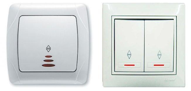
Presence of light indication
There are devices equipped with a chain of lights. It has several functions:
- illumination of the location of the switch (useful when entering a dark room);
- Indication of the contact group switching on;
- In some cases, an indication of a lamp failure.
The light circuit is usually made with LEDs or small neon bulbs. The circuit of the switch with one or two keys and LED are performed according to the same principle.

The current that initiates the illumination of the LED flows through limiting resistor, the light-emitting element itself and the luminaire. When the main contact closes, the illuminating circuit is bypassed and the LED goes out. If an incandescent bulb is used as a light and it has burned out, the circuit will also be open and the LED will not light up at any key position of the device. In two-button devices, the circuit is usually placed in parallel to one contact group.
By contact functionality
Most household switching devices can have a contact group of the following designs:
- conventional (make-before-break);
- Through (changeover contacts);
- Cross-over (two changeover contact groups, connected in a special way).

The last two types are actually switches.
Normal and through-type switches are also available in two- and three-key versions, in which case they have two or three contact groups, respectively. The application of each type of apparatus is described below.
According to the type of wiring
Cables for connecting the elements of the lighting system in the premises are laid in two ways:
- exposed;
- hidden.
The second option wins purely in terms of aesthetics, fire safety and virtually zero chance of damage to the cables. But concealed wiring requires cutting out channels (trenches) in the brick, concrete wall or in the plaster. There are certain restrictions on the installation of conduits:
- you can perform the channels only horizontally or vertically (at an angle of 0 or 90 degrees);
- It is forbidden to cut horizontal entries in load-bearing walls.
Other restrictions and rules can be found in SNiP 3.05.06-85 (SP 76.13330.2012).
Strokes are not necessary if concealed wiring is laid inside a plasterboard partition wall. Open wiring is performed on the studs.

Materials and tools for connecting appliances
The minimum required tool kit for installing switches is as follows:
- Pliers to shorten cables;
- a wire cutter for stripping the insulation;
- a screwdriver set for installing the devices and tightening the screws of the terminals.
If you intend to connect the wires in the distribution box by twisting with subsequent soldering, you will also need an electric soldering iron with a set of consumables, as well as material for the insulation - electrical tape or plastic caps. If you intend to use terminals, you will need spring-type (clamp-type) or screw-type terminals.


If you are installing the wiring from scratch, you will need to make a grommet for concealed wiring. To do this, you will need one of the tools (in order of cost of the appliance, speed and quality of work):
- stubbing cutter;
- grinder;
- hammer;
- chisel with a hammer.
For the installation of sub-sockets in a concrete or brick wall, you must make notches with a drill bit. For exposed wiring, purchase cable ducts or support insulators. To fix them to the wall and ceiling, you will need a drill and dowels.

Wiring diagrams of devices
Depending on the type of device and its application in a particular situation, the connection schemes of switches will differ.
Single-key switch
The connection scheme of the switch with a single button is the most simple. The contacts of the device in one position assemble, and in the other break the electric circuit.

There can be one lamp, or there can be several, if you include them in parallel. They will be controlled synchronously. The main thing is not to exceed the load capacity of the device contacts.
Important! For simplicity, the protective earth conductor PE is not shown in the diagram - it does not affect the functionality of the lighting system, but directly affects the safety. It comes from the switchboard to the lamp and is connected to the appropriate terminal.

Two- and three-button devices
Switches with two and three contact groups switch two or three loads independently. Such loads can be:
- lights located in different rooms or zones;
- Different lighting systems in the same room (main lighting and spot lighting);
- different groups of lamps in a multi-arm chandelier.
In principle, the schemes do not differ (except for the number of keys), but the topology of the laying of cables and the connection in the distribution box will be different.

For example, here is a wiring diagram of a device with three buttons to control three separate lights.

Using a switch through a light fixture with a fan
Ceiling light fixtures combined with a fan are available for sale. There are two options for controlling such devices:
- By means of a single push-button switch;
- by means of a two-button device.
The first option is easier and requires less cable consumption.

But in this case, the fan and the lamp are controlled simultaneously. It is not possible to switch on the airing or the lighting separately.

The second scheme is more complicated and requires cables with more wires. But the fan and the lights are switched separately..
Motion sensor for lighting control
To turn on the light only when there is a moving object (person or vehicle) in the monitored room or area, use motion sensors. Their use provides significant energy savings, and the connection scheme has certain features.

The simplest case is when the motion sensor of two-wire design is used. In this case, its connection does not differ from the usual switch - it is included in the gap of the phase wire.

But many motion sensors need a three-wire connection to power their own circuitry, which in most cases will require a reconstruction of the lighting system.

Therefore, in some cases, you can apply a modified circuit - a diode and a capacitor are added to it. As a result, the three-wire detector can be included in the gap of the phase wire. But this scheme is not always applicable, it depends on the type of luminaire.
You should also take into account that not always the contacts of the motion detector can directly switch the load. In this case, you must connect a low-power switch to the load via an intermediate repeater relay.


Using a Loop Switch
Having two loop-through Devices, you can make a lighting scheme in which you can turn on and off the light from two points. This control system is convenient in long hallways, large warehouses, bedrooms (when you enter the light is off, after going to bed you can turn it off - and vice versa in the morning).

When manipulating one unit, it does not matter what position the other unit is in. You can see from the diagram that you can break and reassemble the circuit with any switch with a cross-over group of contacts.
Use of a cross-over appliance
In T-shaped hallways, double bedrooms, and children's rooms, it may be necessary to independently turn on and off lighting fixtures from three independent locations. On the pass-through devices alone, such a scheme can not be assembled, you will need to use a cross (reverse) switch.

It is obvious from the diagram that any switch assembles or opens a circuit in one of its positions independently of the other apparatuses.

Wiring a backlit apparatus
In the era of incandescent bulbs, the backlight circuit could be overlooked. When off, the small through current had no effect on the operation of the lighting system. This has changed with the advent of energy-saving and LED lamps. In some cases, even a current of a few milliamps is enough to cause unpleasant flickering of the luminaire. There are two ways to combat this phenomenon:
- shunt the light fixture with a resistor or capacitor (it is convenient to put a shunt directly on the lamp socket or chandelier connector);
- if the switch commutes a group of lamps, you can try to replace one lamp in the group with an incandescent bulb.

As a last resort, the backlight circuit can be removed.
Video: Connecting the backlight on a single push-button switch.
Wiring diagram in the junction box
The order of wiring in the junction box depends on the overall scheme of the lighting system, but you can highlight the general principles:
- The cable from the switchboard containing phase L, neutral N and (not always) protective PE conductors is fed into the box;
- neutral and protective (if any) conductors from the box go in transit to the loads;
- The phase conductor has a break and is branched off into as many branches as the loads are supplied;
- the cable to each luminaire contains a phase conductor, as well as N and PE;
- A switching device is connected to the phase gap, a cable with the number of conductors equal to the number of switched loads plus the supplying phase conductor is lowered to it.

A rather complicated variant is shown as an example. A switch with three buttons Controls three lights:
- the box includes a cable with three conductors (including PE);
- to the three-button switch there is a cable with 4 wires (3+power supply);
- to each load goes its own three-core cable (if there is no protective conductor - two-core);
- N and PE conductors are connected and branched in the box.
In the case of feed-through and crossover switches to control lights from multiple locations, most of the circuit is assembled in a loop.

Also in this case, it is possible to wire products without using a junction box.
Video lesson: 5 mistakes when wiring junction boxes.
General approaches to installation
The general order of installation of the switch will be as follows:
- equip the place of installation of the device (for overhead install a cover, for built-in - to make a notch in the wall and mount a sub-socket);
- Cut the cable (shorten, remove the upper sheath, stripping the conductors);
- Connect the mounted light switch to the conductors according to the chosen scheme (this will be a good help to have a color-coded wires);
- Connect the conductors in the distribution box;
- install the switch in place and secure it (with self-tapping screws, by unfastening the petals);
- Install in place the decorative plastic parts.

The main principle of installation is the maximum safety of the work. To do this, the connection of any electric switch should be made with the voltage off. In this case, everything will go well and the switch will serve for a long time.