Details about the connection methods of LEDs
In our lives, LEDs are steadily gaining the upper hand over other sources of artificial light. But while incandescent lamps can be connected directly to the power supply, the connection of LED and discharge lamps requires special measures.
Connecting a single LED does not cause any problems. And to include from several units to hundreds - not as easy as it seems.
A bit of theory
LEDs require a constant voltage or current to work properly. They must be:
- Constant in direction.. That is, the current in the LED circuit must flow from the "+" of the voltage source to its "-" when the voltage is applied.
- StableStable, i.e. constant in magnitude, for the diode's operating time.
![Details about the methods of connecting LEDs]()
- Non-pulsating - After rectification and stabilization, the voltage or current constants must not fluctuate periodically.
![Voltage waveform diagram]() Schematic diagram of the voltage waveform at the output of a two-half-period rectifier when filtered by an electrolytic capacitor (black and white rectangles marked "+" in the diagram). Dotted line - voltage at the rectifier output. The capacitor is charged to the half-wave amplitude and gradually discharged at the load resistance. The "steps" are the pulsations. The ratio of the step and half-wave amplitudes as a percentage is the ripple factor.
Schematic diagram of the voltage waveform at the output of a two-half-period rectifier when filtered by an electrolytic capacitor (black and white rectangles marked "+" in the diagram). Dotted line - voltage at the rectifier output. The capacitor is charged to the half-wave amplitude and gradually discharged at the load resistance. The "steps" are the pulsations. The ratio of the step and half-wave amplitudes as a percentage is the ripple factor.


For LEDs at first we used available voltage sources - 5, 9, 12 V. And the operating voltage of p-n junction is from 1.9 to 2.4 to 3.7 to 4.4 V. Therefore, switching a diode directly is almost always a physical burnout from overheating with a high current. The current must be to limit the current with a current limiting resistorThis is a good way to limit the current with a current-limiting resistor.
You can put several LEDs in series. Then, if they are in a chain, the sum of their direct voltages can be almost equal to the power supply voltage. And the remaining difference is "extinguished" by dissipating it in the form of heat on a resistor.
When there are dozens of diodes, they are connected in series circuits, which are included in parallel.
LED pinout
LED polarity - anode or plus and cathode - minus is easy to determine from the pictures:


Diagram of connection of LED
LEDs are fed by DC voltage. But the peculiarities of nonlinear dependence of its internal resistance requires to keep the operating current in a narrow range. At a current of less than the rated current decreases luminous fluxAt higher - the crystal overheats, the brightness of the luminescence increases, but the "life" is reduced. The easiest way to extend it is to limit the current through the crystal, including a current-limiting resistor. For high-power LEDs it is economically unprofitable, so they feed a constant current from a special source of stable current - driver.
Series connection
An LED is a rather complex lighting device. It operates from a secondary DC voltage source. If the power is more than 0.2-0.5 W, most LED devices use current sources. They are not quite correct, in the American manner, called drivers. When diodes are connected in series, they often use power supplies at 9, 12, 24 and even 48 V. In this case, build a daisy chain, which can be from 3-6 to several dozen elements.
When connected in series in a chain, the anode of the first LED include through a current-limiting resistor to the "+" power supply, and the cathode - to the anode of the second. And so the whole chain is connected.
For example, red LEDs have a direct operating voltage of 1.6 to 3.03 V. At Upr. = 2,1 В of one LED on the resistor at 12 V source voltage will be 5.7 V:
12 V - 3×2,1 V = 12 - 6,3 = 5,7 V.
And already 3 chains in series are connected in parallel.
Table showing the direct voltage of a LED as a function of the color of its glow.
| Glow color | Working voltage, direct, V | Wavelength, nm |
|---|---|---|
| White | 3,5 | Broad spectrum |
| Red | 1,63–2,03 | 610-760 |
| Orange | 2,03–2,1 | 590-610 |
| Yellow | 2,1–2,18 | 570-590 |
| Green | 1,9–4,0 | 500-570 |
| Blue | 2,48–3,7 | 450-500 |
| Purple | 2,76–4 | 400-450 |
| Infrared | Up to 1.9 | from 760 |
| Ultraviolet | 3,1–4,4 | up to 400 |
When LEDs are connected in series, the currents through the LEDs will be the same and the drop across each element is individual. It depends on the internal resistance of the diode.
Properties of the series connection:
- Breakage of one element will cause all to turn off;
- shorting - redistributes its voltage to all the remaining ones, on them increases the brightness of the glow and accelerates degradation.
Recommended: How to know how many volts a LED is
Parallel connection
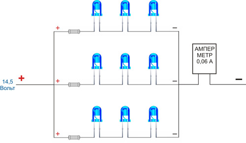
In this LED wiring scheme, all the anodes are connected between themselves and to the "+" power source, and the cathodes - to the "-".
This connection was on the first LED lights, strips and strips when powered by 3-5 volts.

If the burnout occurs with a p-n junction closure, the entire battery voltage will be applied to resistor R1. It will overheat and burn out.


In the picture:
- The gray bars are current-carrying bars, i.e., wires without insulation;
- blue cylinders with rounded end - cylindrical LEDs with a lens at the end;
- red - resistors to limit the operating current.
It would not be correct to connect all the diodes to one resistor. Because of the variation of the characteristics of LEDs, even in one batch can reach from 50 to 200% or more, through the diodes may flow current, which will differ at times. Therefore, they will shine and load differently as well. Later, the busiest, brightest glowing one will burn out or degrade to near extinction, losing 70-90% of its luminous flux. Or it will change from white to yellow.

Mixed
Combined or mixed wiring is used to create LED arrays consisting of many tens or hundreds of elements or frameless crystals. The best known of them are COB matrices.

The supply voltage and operating current will be less than the rated operating current when combined. Only under this condition, the matrix will more or less work for a long time. At the rated current, the weakest link will burn out quickly and the others will start to burn out gradually. It will end with breakages in the series circuits and short circuits in the parallel circuits.
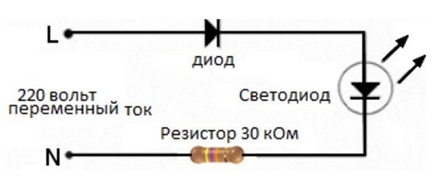
Connecting a light-emitting diode to 220 V
If you energize the LED directly from 220 V with a limitation of its current, it will shine with the positive half-wave and go out with the negative. But this is only if the reverse p-n junction voltage is much higher than 220V. Usually it is around 380-400V.
The second way to turn it on is with a quenching capacitor.

WARNING! Most circuits with a direct connection to the 220 V mains have a serious drawback - they are dangerous for the human to be struck by high voltage - 220 V. Therefore, they should be used carefully, with careful insulation of all current-carrying parts.
Detailed information about connecting the LED to a 220 V mains described here.
How to power diodes from a power supply
The most popular transformerless switching power supplies provide 12 V with current, short circuit, overheat and other protections.
So you connect the LEDs in series and limit their current with a simple resistor. The chain includes 3 or 6 diodes. Their number is determined by the direct voltage of the diode. Their sum for current limitation must be less than the output voltage of the PSU by 0.5-1 V.

Features of connecting RGB and COB LEDs
LEDs with the abbreviation RGB - are polychrome or multicolor emitters of light in different colors. Most are assembled from three LED crystals, each emitting a different color. Such an assembly is called a color triad.
RGB-LEDs are connected in the same way as conventional LEDs. In each body of the multicolor light source has one crystal: Red - red, Green - green and Blue - blue. Each LED corresponds to a different operating voltage:
- Blue - from 2.5 to 3.7 V;
- Green - from 2.2 to 3.5 V;
- Red: 1.6 to 2.03 V.
Crystals can be connected together in different ways:
- with a common cathode, i.e., the three cathodes are connected to each other and to a common lead on the case, and the anodes each have their own lead;
- with a common anode - respectively, for all the anodes, the lead is common, and the cathodes are individual;
- independent pin assignment - each anode and cathode has its own pin.
Therefore, the ratings of current-limiting resistors will be different.


In both cases, the body of the diode has 4 wire pins each, contact pads in SMD LEDs or pins in the "piranha" body.
In the case of independent LEDs there will be 6 pins.
In the case of SMD 5050 crystals-LEDs are arranged as follows:

Wiring COB LEDs
The abbreviation COB - are the first letters of the English phrase chip-on-board. In Russian it will be - element or crystal on the board.
The crystals are glued or soldered onto a thermally conductive substrate of sapphire or silicon. After checking that the electrical connections are correct, the crystals are filled with yellow phosphor.
COB type LEDs - are matrix structures consisting of tens or hundreds of crystals, which are connected in groups with combined inclusion of semiconductor p-n junctions. Groups are sequential chains of LEDs, the number of which corresponds to the supply voltage of the LED matrix. For example, at 9 V it's 3 crystals, at 12 V it's 4.

Circuits with series connection are connected in parallel. In this way the required power of the matrix is gained. Blue luminescent crystals are filled with yellow phosphor. It re-emits the blue light into yellow, obtaining white light.
The quality of the light, i.e. color rendering is regulated in the production process by the composition of the phosphor. One- and two-component phosphor gives low quality as it has 2-3 emission lines in the spectrum. Three- and five-component - quite acceptable color rendering. It can be up to 85-90 Ra and even higher.
Connecting this type of light emitters is not a problem. They are plugged in like a normal high-power LED, powered by a standard rated current source. For example, 150, 300, 700 mA. The manufacturer of COB matrices recommends choosing current sources with a reserve. It will help when putting a COB matrix light into service.